Buy all your VW California Accessories at the Club Shop Visit Shop

Elevating roof hydraulic pump repair

What format would you like the CAD model in?
I might be interested too.
I use AutoCAD 2020, and could use a .DWG file.

Mine is still in repair.
My oil reservoir was full of debris (probably rubber seals), so I have someone to change all the removable inner parts and seals.

Good job it worked out ok for you!

Hi, just wondering to know how I could bleed (take air off) from pump. Dont't know exactly which screw I need to touch. Thanks
dakpomp.jpg
 
Congratulations on an impressive investigation and repair!
How do you access the pump like this?
Have you removed the internal ceiling lining to expose all the workings?
There was a lot of work and help of @TripleBee.

You have to remove headlining, pilar A and B cover + frame for sliding door to the roof. TripleBee posted excellent guideline for it. In case you will need any help let me know. I have a lot of pictures from action. :)
p.s. Always cover your interior with some foil during beading.
 
There was a lot of work and help of @TripleBee.

You have to remove headlining, pilar A and B cover + frame for sliding door to the roof. TripleBee posted excellent guideline for it. In case you will need any help let me know. I have a lot of pictures from action. View attachment 68507
p.s. Always cover your interior with some foil during beading.
Ah yes, I'm catching up. i've found Triplebee's excellent post now.
Cheers.
 
Congratulations on an impressive investigation and repair!
How do you access the pump like this?
Have you removed the internal ceiling lining to expose all the workings?
One way of access/remove the roof hydraulic pump, is to remove the control panel in the ceiling, then the light fixture, and the frame and so on. The pump is mounted behind some styrofoam and is hold in place with a u-shaped bracket that strapped the pump.
It is then possible to fiddle out the pump thru the opening.
I’ve done this 2-3 times when filling hydraulic oil in my California...
 
We got the local dealer to investigate our roof errors and the mechanic there has worked on Calis in the UK and he said that the official VW procedure for accessing the roof control and pump is to remove the roof, not the interior lining.

Does anyone know if this is correct? It seems a lot messier than TripleBee's method.
 
The only way to get to the roof pump is to remove the head lining. How are you going to remove the roof when the pump doesn't work anymore?
And if you remove the roof, how are you going to get to the pump that is underneath the head lining?
 
Thanks, that’s what I figured and eWin has confirmed, so I am in the process of following your headlining removal steps now... yay.
 
We got the local dealer to investigate our roof errors and the mechanic there has worked on Calis in the UK and he said that the official VW procedure for accessing the roof control and pump is to remove the roof, not the interior lining.

Does anyone know if this is correct? It seems a lot messier than TripleBee's method.
I would find a new dealer! They’d have to cut the front “cap” off to access the pump through the roof.
 
Yeah, I would but The other dealer in town is much worse. having taken the roof lining out, I guess I’m at the point of troubleshooting this for myself.
 
Yeah, I would but The other dealer in town is much worse. having taken the roof lining out, I guess I’m at the point of troubleshooting this for myself.
You can convert the roof to Manual Operation. A Forum member has done this and prepared a How To document with parts details and measurements etc:
 
Yep, I know, I have the instructions already but our roof works fine apart from when it gets hot so I would rather fix that and keep it “original”.
 
Hi.

My '07 T5 California has an issue with the elevating roof. Symptoms are that the roof opens fine, but when lowering it only lowers one side. Concluded the problem is with the hydraulic pump unit since when I swapped ram hoses between left and right on the pump side, the symptom moved to the other ram.

Since the pump itself is generating hydraulic flow, it appears that something is wrong with either a canal, restrictor, or some kind of flow balancing mechanism. Given that there are few moving parts, I find it unlikely that anything is actually physically damaged or worn. I reckon it is a fair chance that something is either stuck or clogged due to contamination. Given that the price for a new pump is hideous, I decided to try a partial disassembly and then try to rinse the housing.

Status is that I have disassembled all the parts that can easily be disassembled (some springs/balls and a couple of sliding pistons). Left in the block are some pressed in sleeves, and what looks like calibrated adjustment valves. I have not touched anything of this.

I think I will try to submerge everything in a fluid in an ultrasonic cleaner. That should hopefully loosen any trapped contamination. Then rinse/flush somehow afterward. The question I have is what kind of fluid can be used? Since some parts are left in the block It is difficult to ensure all cleaning fluid is properly flushed out. Ideally, it should be compatible with the hydraulic fluid (which is 150GBP per liter by the way).

Any suggestions?
Excellent really interesting,I spoke about this a few weeks ago and said probably the pumps are perfect and probably the problems are related to debris trapped in a check valve, not sure your hydraulic drawing is right but what you usually have is check valves on both piston sides of the cylinder not rod side this is to stop the cylinder falling when the pump turns off,then they usually have pilot feeds to them that lift the ball check valve off it’s seat which then allows the fluid from the full piston side return back to the tank.
the oil in my opinion should be a mineral hydraulic oil , seals won’t be affected by mineral oils, the other hydraulic oils are glycol water based which does require different seals. If you put glycol hydraulic oil into a mineral system big issue will follow but mineral into glycol system won’t do any damage.The grade is the issue viscosity ,that system will probably run on 32 or 46 but that depends on the pump type ie piston ,gear, or vane not sure what that is.?
the debris I think is probably from when the hoses are manufactured they cut the hoses to length with a chop saw then crimp the fittings on , small chips produced from the sawing process drop into the hose ,really they should be flushed but I bet they dont , i bet this is the reason why even new vans are having issue.

hope this helps
 
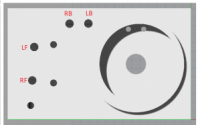
All the letters in the schematic are referenced to letters to the external ports on the manifold according to the picture below.

Pump in and out port is actually int the center of the big circular feature. I have not drawn that detail.

Here is what I believe the various components are:
A = 3 way Spool valve
B = Ball check valve
C = Pilot operated check valve? Side 1
D = Directional valve for pump flow? Side 1
E = 3-way spool valve
F = Emergency close valve
G = Directional valve for pump flow? Side 2
H = Pilot operated check valve? Side 2
I = Adjustable restrictor or ball check valve
J = Adjustable restrictor or ball check valve
K = Pilot operated check valve
L = Pilot operated check valve
M = Ball check valve
N = Ball check valve
O = suction pipe
P = adjustable restrictor or ball check valve
Q = adjustable restrictor or ball check valve

Ram connection ports:
RF = Right Front
RB = Right Back
LF = Left Front
LB = Left Back

BTW, I have tried cleaning the manifold as good as possible using brake cleaner (isopropyl alcohol basically) in combination with compressed air. I don't know if it helped or not but could not see any obvious debris exiting from anywhere.

View attachment 60433
This is really helpful, thank you!

One quick question.

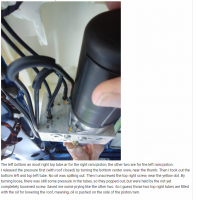
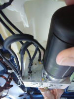
I have just taken the pump out of my 17MY Van, noting the pipes have numbers printed on them and also using TripleBees's pictures as cross reference.

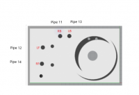
I think the pipe ports are slightly different from what is in your diagram. Is is possible that RB and LB are the other way around? On My van Pipe 11/12 Are the Left Pair and 13/14 are the Right Pair.

1606643471941.png
TripleBee's Picture & Words

1606643707413.png


Thanks Andrew

1606643450502.png

1606643488060.png
 
Could be that they are swapped. The ports that pipe 11 and 13 connects to is just going into the same cavity/pipe anyway so it does not really matter.

Sent fra min SM-G975F via Tapatalk
 

Similar threads

Back
Top