Fitting a Solar Camper Solutions 100W Panel to a MY21 6.1 Ocean

dspuk

dspuk

Dave
Super Poster
Lifetime VIP Member
Messages
2,327
Location
United Kingdom
Vehicle
T6.1 Ocean 204
Part 1.

After deciding to buy one of the @Roger Donoghue kits I thought it could be of benefit to any others with my specific spec to see how I did it. Everything is more or less in Rogers instructions, but I did find them a challenge to understand due to how they seem to have evolved over time with addendums etc. The Bed Bus video was also helpful, but not an Ocean so in fact a reasonable amount different. There are a LOT of images in this thread, 28 to be exact, but I have shrunk them to keep the page loading optimised. If anyone wants a larger size, LMK. For info I am an ex-Army mechanic and used to work in Nissan, so a reasonable knowledge of the topic. I was still a little bewildered at first but eventually realised there are just three steps:

1 - Install a MPPT charger.
2 - Put a panel on the roof and wire it to the MPPT charger.
3 - Put a cable on the battery and attach that to the MPPT charger.

Everything else in between is making it look neat.

Ok - After reading the instructions a dozen times and surveying the van, I decided to install from the battery first. It made sense to me to start at the bottom and work up. Tools I used for the job - 10mm and 13mm sockets, phillips screwdriver and electrical screwdriver. I also used loom tape to tidy and make neat and have ordered some helicopter tape to go under the curly cable. Less for protection and more to reduce friction. everything else you need is in Rogers jiffy.

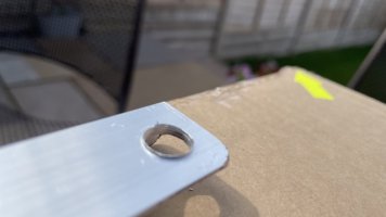
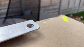
Fiirst though I got everything out. There were some burrs on the holes for the panel caddy to decided to make them right first - deburred with a large drill bit (13mm).
1 - Burr Medium.jpeg
2 - Deburr Medium.jpeg

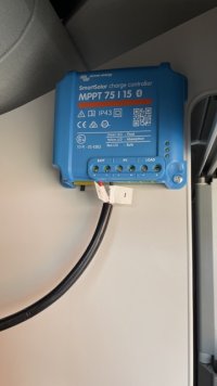
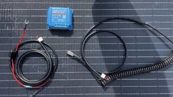
Then I laid it all out to have a look. Here we have the panel, MPPT charger and the two cables. Curly is from panel to MPPT, the straight with a red wire is battery to MPPT.
3 - Layout Medium.jpeg

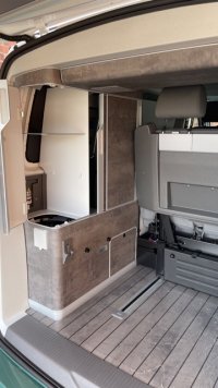
Next step was to prep the back. This involved removing all shelves and the whole rear unit. It's easy enough - release the catches, slide and then tilt the right side up and walk backwards slowly.
4 - Cupboard Prep Medium.jpeg

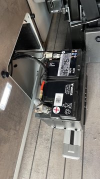
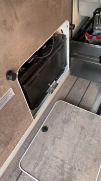
Then take off the battery cover and remove the battery. To do this you need a 13mm socket to remove the battery foot clamp, slide the battery towards the rear of the van (there is a 10 mm gap to do this) and then tilt the front up and slide slowly out. Keep it tilted as the space is tight and there is something above the battery.
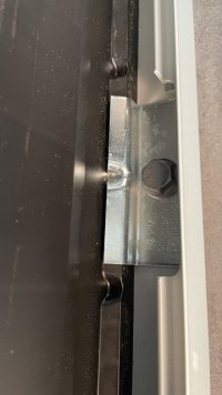
5 - Battery Cover Medium.jpeg6 - Battery Bolt Medium.jpeg7 - Battery Out Medium.jpeg

Then drop a piece of string as shown down the side of the breaker fuse unit and push the end of the battery MPPT cable though the battery hatch until it comes out near the gas canister. It's the same gap as comes from the breaker unit, so easy enough to find. Then attach to the string and pull though as shown. I tried without the string and in the end the string was quicker.
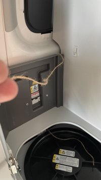
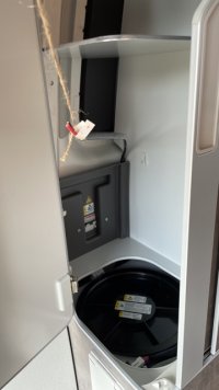
8 - String In Medium.jpeg9 - Cable Pulled Medium.jpeg

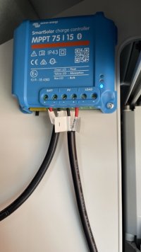
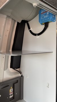
Then I put the MPPT on. I was going to put this in with the battery but there is no room and the cables are not the right length for that. It was also best to put here in case of future maintenance and access. I used the short screws supplied with a little pressure and just screwed into the rear shelf panel. Easier than it looked. Tight space for the top two, use a stubby if you can but possible if not.
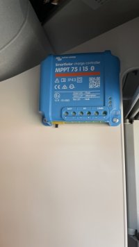
10 - MPPT on Medium.jpeg

See next post for part 2 (10 file insert limit).
 
Last edited:
Part 2

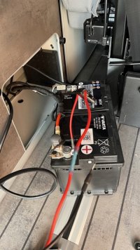
Next step was to attach the cable to the battery. I was a little confused here at first but the instructions are right. Just just need to attach the red to the + bolt as described. Leave the black off - you put this on when the battery is back in place onto the clamp bolt. You need a 10mm socket for the battery positive clamp bolt.

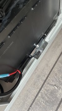
When this is done slide the battery back in and then clamp the black cable as shown using the clamp bolt. Effectively you “earth” the negative cable rather than attaching to the actual battery. Just keep your cover off and the spare MPPT wire to hand as you need to move it about when doing the final fit and finish.

11 - Red On Medium.jpeg12 - Bolt On Medium.jpeg

Then I did a test before routing the wire and just checked that power from the battery was going to the MPPT. This seemed fine - the blue light at the bottom of the unit flashes. Then removed it again ready to route.

13 - Test Battery In Medium.jpeg

Ok - bottom done, but not tidy, I then started on the top.

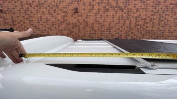
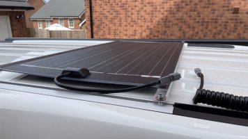
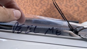
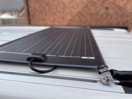
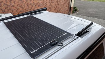
First the panel position is about 50cm from the rear - as shown here. Then I attached the curly cable to the clip, also making good the straight edge from the cable with the ties onto the aluminium panel bar, as per the instructions. I also fitted the protector sheet under the clip - why not.

25 - Panel Position Medium.jpeg14 - Coil Prep Medium.jpeg15 - Peel Medium.jpeg16 - Peel On Medium.jpeg
17 - Coil On Medium.jpeg

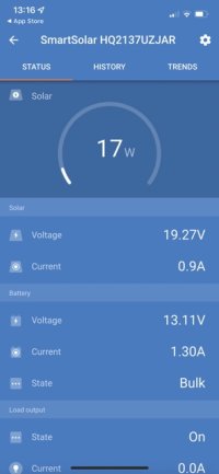
With this all in position I then decided to test the MPPT again, voila, power to the batteries from the panel. The blue light is permanently on when working. Not much charge - but it was enough to have charged the battery by end of day. Not very sunny today!

18 - Test Panel Medium.jpeg28 - It works Medium.jpeg

Final steps in part 3.
 
Last edited:
Part 3

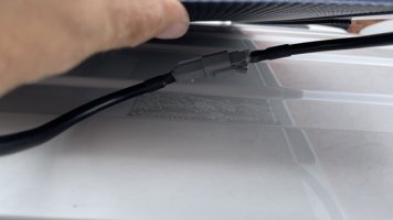
Ok - now the part that took the most time - routing everything to look neat. Starting with the top - I drilled a 7mm hole into the base of the grommet. The cable is 8mm so 7 keeps it watertight. Then threaded it all through to give me all the cable the other side of the grommet but not in the van yet.

19 - Grommet Hole Medium.jpeg

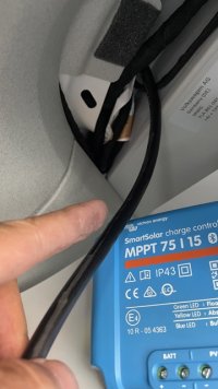
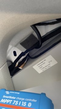
Then was the hard part - trying to get this top cable through into the right position. For the life of me I could not get it above the corner of the cupboard where I wanted it so what I did in the end was follow the line of the existing cable in the grommet which brings you out further back, first picture. I was then able to loop that back and find a gap from there that took me to the top corner of the rear corner cupboards. The second pic where the cable is looping back. Not ideal and may try again another day. Might not make much sense but a lot of trial, error and swearing. I could have left it where it was and just routed in a straight line down the left side of the MPPT, but that would have left a wire showing that could get caught and I would have had to cross the wires to fasten them into the MPPT terminal clamps and my OCD would not allow a crossed wire so it had to go to that corner in the end.

20 - Cable In Medium.jpeg21 - Cable Looped Medium.jpeg

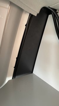
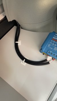
Now I was able to have both cables neatly routed to the to corner I wanted - just to the side of the MPPT. There was a natural channel for the bottom cable (it’s to the left side of the black panel) so I was able to use that and cover with some loom tape to make neat and keep tight to the edge. Just feed the cables though till they are the length you want and pull the rest into the cavity or the battery compartment.

22 - Cable Route Medium.jpeg23 - Top Cable Medium.jpeg24 - Cables in Medium.jpeg

Note - the bottom clip near the fuse breaker cover is tight to the bottom shelf when you put back in, but it does fit.

With all that done you can replace the battery cover, coiling any slack cable you have left from final fitting to length to the left side of the battery, put the frame back in and your shelves back in place.

Voila.

*Note - see addendum - curly cable now ok.Ish.*

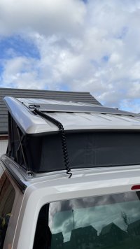
The curly cable is not perfect yet IMHO - it caught a couple of times bringing the roof back down and would have ended up stuck in the seal. It also feels tight when the roof is up and I worry that the stress will pull the joint Roger has made. I may have to play with its position and the clips to get it right so that it works as I assume was intended. But, all in, very pleased and was able to have the batteries fully topped up by end of day.

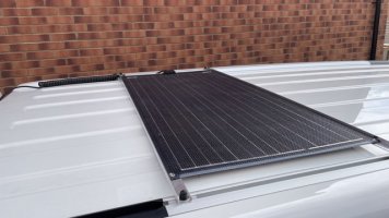
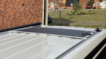
Any questions - Just LMK. The finished panels in position and powering the batteries.

26 - On 1 Medium.jpeg27 - On 2 Medium.jpeg
 
Last edited:
Thanks for sharing. If nothing else gives confidence that it can work! (I have the identical vehicle, so likely to follow suit.)
 
Fitted mine a couple of months ago. Wish I'd have thought about drilling a hole in the grommet, instead of cutting it......Great idea.
 
Very well explained and with photos, I may have a go myself.:thumb
 
Fitted mine a couple of months ago. Wish I'd have thought about drilling a hole in the grommet, instead of cutting it......Great idea.
Did you have the same issues routing that top cable?
 
Think you need to pull your curly cable thru a bit more (to leave just curly exposed on roof, hardly any straight cable), then taped connection on the cable will sits protected inside inside the van. This should also stop the cable from getting trapped in the roof.
 
Think you need to pull your curly cable thru a bit more (to leave just curly exposed on roof, hardly any straight cable), then taped connection on the cable will sits protected inside inside the van. This should also stop the cable from getting trapped in the roof.
Cheers - I had wondered but Rogers image of the cable tie on the hinge looked like it was a straight piece so hence I left out a bit but that makes sense and will give it a try.
 
Great write up, sure it will give others confidence to do this.
When I did mine I also added a strip of clear helicopter tape on the roof directly under where the curly cable lays, just to add protection from scratches etc.
 
My experience is pretty well the same as yours, including some choice words while getting the curly cable through to the back of the cupboard. My curly cable is as described by @Ch1pbutty and it works as it should.
 
Part 4 - Addendum(s).

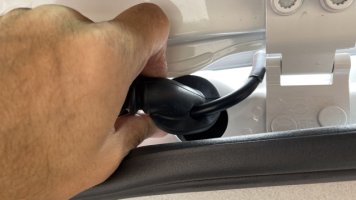
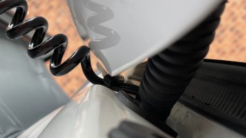
As advised by @Ch1pbutty have repositioned cable and works as intended. Have dropped some pics below but basically bring the first coil all the way back to the hinge and cable tie there. Going down works fine and you can hear the cable slither back. Going up is also fine but it still sits under a little tension due to friction of the cable on the roof not allowing it to uncoil as easily. Possible helicopter tape as advised by @Mr T will reduce that. I found on testing a flick of the cable releases the tension which you can do on site the first time round the back of your van after opening. Now just to one day get back to the top cable routing.
780D2B22-60B4-4BA2-903D-D6F8056D2614.jpegFE522AB5-CA43-411A-9319-5D34B7324E93.jpegCE4AD525-589D-42F5-A03E-311F0ECC9771.jpeg
 
Thanks for sharing the install and pictures, gives me confidence that I should be able to undertake this DIY install, when my van eventually arrives.

Is 100w enough or should I go two panels.
 
Thanks for sharing the install and pictures, gives me confidence that I should be able to undertake this DIY install, when my van eventually arrives.

Is 100w enough or should I go two panels.
Lots of chat on this but advice from Roger is 100w is fine for 80% or more of peoples use. For me I may one day add an extra panel but as they are in series you can do this later very quickly and the cost is effectively the same. I'd start with 100 and go 200 later if you have a need.
 
Thanks for sharing all the detail this is will deffo come in handy soon as I have just took the plunge and ordered a couple of panels from Roger, however i wanted to know how you could make it so you can use the internal plug at the end of the counter? any ideas anyone?
 
Thanks for sharing all the detail this is will deffo come in handy soon as I have just took the plunge and ordered a couple of panels from Roger, however i wanted to know how you could make it so you can use the internal plug at the end of the counter? any ideas anyone?
You can’t. There is, AFAIK, no way to get enough power from one panel into the batteries to refill them as fast as most appliances would drain them. If you need to use off grid, a laptop for instance, you can use the inverter socket. I read last week that a 1000W kettle would drain your batteries in minutes. Sure someone else has tried though but the sort of internal rewiring needed for this would be beyond what I would want to do or need. This link helpful - https://www.camperlands.co.uk/camping-inverters-leisure-batteries/
 
Part 3

Ok - now the part that took the most time - routing everything to look neat. Starting with the top - I drilled a 7mm hole into the base of the grommet. The cable is 8mm so 7 keeps it watertight. Then threaded it all through to give me all the cable the other side of the grommet but not in the van yet.

View attachment 98544

Then was the hard part - trying to get this top cable through into the right position. For the life of me I could not get it above the corner of the cupboard where I wanted it so what I did in the end was follow the line of the existing cable in the grommet which brings you out further back, first picture. I was then able to loop that back and find a gap from there that took me to the top corner of the rear corner cupboards. The second pic where the cable is looping back. Not ideal and may try again another day. Might not make much sense but a lot of trial, error and swearing. I could have left it where it was and just routed in a straight line down the left side of the MPPT, but that would have left a wire showing that could get caught and I would have had to cross the wires to fasten them into the MPPT terminal clamps and my OCD would not allow a crossed wire so it had to go to that corner in the end.

View attachment 98545View attachment 98546

Now I was able to have both cables neatly routed to the to corner I wanted - just to the side of the MPPT. There was a natural channel for the bottom cable (it’s to the left side of the black panel) so I was able to use that and cover with some loom tape to make neat and keep tight to the edge. Just feed the cables though till they are the length you want and pull the rest into the cavity or the battery compartment.

View attachment 98547View attachment 98548View attachment 98549

Note - the bottom clip near the fuse breaker cover is tight to the bottom shelf when you put back in, but it does fit.

With all that done you can replace the battery cover, coiling any slack cable you have left from final fitting to length to the left side of the battery, put the frame back in and your shelves back in place.

Voila.

*Note - see addendum - curly cable now ok.Ish.*

The curly cable is not perfect yet IMHO - it caught a couple of times bringing the roof back down and would have ended up stuck in the seal. It also feels tight when the roof is up and I worry that the stress will pull the joint Roger has made. I may have to play with its position and the clips to get it right so that it works as I assume was intended. But, all in, very pleased and was able to have the batteries fully topped up by end of day.

Any questions - Just LMK. The finished panels in position and powering the batteries.

View attachment 98551View attachment 98552
Thank you for sharing, great pictures that are really informative. I plan to instal a couple of panels myself and you efforts are really going to be a help to me.

Thanks again
 
Thanks for sharing the install and pictures, gives me confidence that I should be able to undertake this DIY install, when my van eventually arrives.

Is 100w enough or should I go two panels.
Depends what you want the solar to do and how you use your van.

Each panel just extends the time before you need to drive or plug-in - but with enough you can get to a point where you cover your daily needs in summer.

A Cali roof isn't big enough to hold enough solar to be totally off-grid in winter, i.e. park up indefinitely with a fridge/heating running and no shore-power.

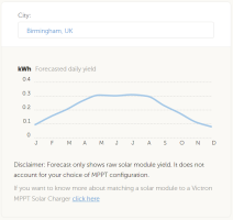
If you go here ... https://www.victronenergy.com/mppt-calculator and enter the details of your system and where you use your van, it will give you an idea of what to expect as output from the solar system per day.

100W solar in Birmingham U.K. will produce this graph ...

1661772570563.pngThis is a basis for calculation, and is an average, it could be a lot better or it could be a lot worse depending on weather, orientation and objects casting shadows.

A Cali fridge uses about 0.4 kWh a day on setting 4 if full and down to target temperature in an ambient of around 20°C.

PS: For me off-grid means fridge on 24/7 and charging various devices like laptop, phones, drones, cameras. For this 310W solar allows me to park up without a hook-up indefinitely in summer in the centre of Europe.
 
You can’t. There is, AFAIK, no way to get enough power from one panel into the batteries to refill them as fast as most appliances would drain them. If you need to use off grid, a laptop for instance, you can use the inverter socket. I read last week that a 1000W kettle would drain your batteries in minutes. Sure someone else has tried though but the sort of internal rewiring needed for this would be beyond what I would want to do or need. This link helpful - https://www.camperlands.co.uk/camping-inverters-leisure-batteries/
Thanks will get an ecoflow delta mini i think and hook it up so charges both leisure and then the EF.
 
Thanks will get an ecoflow delta mini i think and hook it up so charges both leisure and then the EF.
The EF could be charged via the "load" output on the Victron, but you would have to replace the cables to the battery with heavier gage. To be safe in a vehicle you should fork out the extra cash for a power station with a LiFePO4 battery.
 
Fabulous post mate, thank you so much. Still waiting on our October’21 Ocean order but this will be one of the first jobs when it eventually arrives and I’ll be using this as my instructions. Thanks!
 
Thanks for posting. Fitted my panel over a year ago and have had no problems with the curly cable. Positioned so it could account for raising the roof. Used a round hand held cutter to produce a neat hole through the rubber slightly smaller than the cable. Tight fit and when in position sealed with rubber sealant. I fitted the unit in the top cupboard. Easy to access. An important thing to avoid is over tightening of the isolator nut. I did this and cracked it. Have since replaced. The other important thing is to take care not to damage the fuse under the nut. If you do this only one battery will charge. Excellent panels giving sufficient power to be off grid using the fridge without a problem
 
Thanks for posting. Fitted my panel over a year ago and have had no problems with the curly cable. Positioned so it could account for raising the roof. Used a round hand held cutter to produce a neat hole through the rubber slightly smaller than the cable. Tight fit and when in position sealed with rubber sealant. I fitted the unit in the top cupboard. Easy to access. An important thing to avoid is over tightening of the isolator nut. I did this and cracked it. Have since replaced. The other important thing is to take care not to damage the fuse under the nut. If you do this only one battery will charge. Excellent panels giving sufficient power to be off grid using the fridge without a problem
Thanks for update and the tips Paul,
I am following the solar threads closely at the moment (thanks to all posters)as this is to be my next project.
currently I have acquired a couple of flexi panels and now have a Victron controller.
What I am trying to source from the uk is a roof mounting plate (or two smaller)that follows the form of the roof On my 2016 Ocean.

Thanks again Paul, great to hear yours are working so well.
 
Great thread. You should consider working for Haynes :)
I’ve considered fitting a solar panel but will wait and see if I can manage with the two leisure batteries first. But if I do fit solar then I’ll sure use your instructions and images.
 
Back
Top