OEM T6.1 REAR SHOWER SYSTEM - A GUIDE TO PARTS-SOURCING & FITTING
PART I of V
Please see 'CORRECTION 18-Aug-22' & 'UPDATE 18-Aug-22' in fitting guide below
Note there are multiple photo references throughout this guide - use the references (‘px’) to find the pictures (which have had to be split onto multiple pages due to site limits)
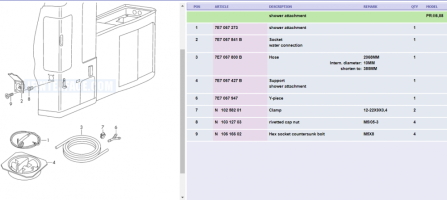
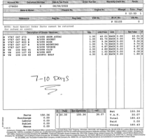
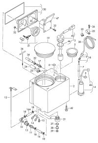
There is also for reference a VW OE item shower kit parts list*, with a quote from my dealer for those same parts, as well as a water system exploded diagram** (*/** for which thanks to the originators!).
So to start, here is my kit list and the sources for the parts I used:
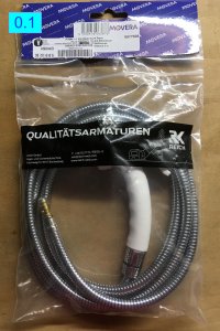
1. OE rear bulkhead shower attachment fitting (inc. switch) + 2m shower head-and-hose ass’y (
p0.1)
€75.41 delivered
https://www.roadloisirs.com/en-GB/reich-charisma-cold-water-socket-shower-head-kit_CW10503.htm
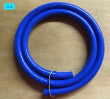
2. 10mm bore x 1m blue water hose - very similar to OE, but not quite so stiff (
p0.2)
£3.18 delivered
https://www.ebay.co.uk/itm/122377057576
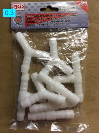
3. Water pipe T-piece (to feed both galley sink / shower) - looks exactly like pictures of OE part (
p0.3)
£7.21 delivered
https://www.amazon.co.uk/gp/product/B015EKYNZI/?tag=unique09f-21
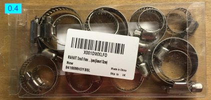
4. Hose clips - quality s/s parts (
p0.4)
https://www.amazon.co.uk/gp/product/B0969JZHSV/?tag=unique09f-21
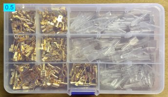
5. 1/4” electrical spade terminal & shroud kit (
p0.5)
£6.59 delivered
https://www.ebay.co.uk/itm/333917138391?var=542976809889
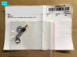
6. Blue tell-tale shower-on LED (
p0.6)
£3.35 delivered
https://www.ebay.co.uk/itm/264074262215
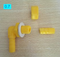
7. OE right-angle water tank outlet fitting (I broke mine removing the hose!) (
p0.7)
£10.20 collected from VW
assembly no. 8 on water tank parts exploded diagram
You can carry out the required steps in different sequences, so I have just recorded what I did.
Once you get going, the options to vary the order become obvious.
There are 3 distinct jobs:
1. BREAK AND TEE THE WATER TANK OUTLET HOSE
2. INSTAL BULKHEAD FITTING ON NSR CUPBOARD FACE & CONNECT PLUMBING
3. CONNECT SHOWER SWITCH TO SINK TAP SWITCH
1. Break and tee the water tank outlet hose
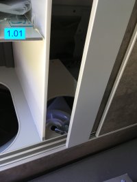
To get access to the water tank I set about removing the sliding rear cupboard and wardrobe doors (
p1.01) - however, I suggest you
DO NOT try this - whilst the small (M2,5 Allen head) screws on the bottom fittings unscrew quite easily, those on the upper brackets have fearsomely strong Loctite, and you will likely round the Allen sockets. Instead I realised I should simply remove the shelf ass’y in the boot, put the rear bench at its max rear position, fold it flat (i.e. bed mode), then I was able to kneel close to either cupboard opening and get at everything I needed to from ahead, alongside, or behind.
I removed the shelf above the gas bottle, unscrewed the bung, and took out the odds and sods I store there, then lifted the smaller round closing bung in the hanging wardrobe, finally the plastic finisher panel which goes behind and provides a guide for the 3-slot sliding blind in the area of the NSR window glass. The 3x 2-part plastic barbed fasteners come out by screwing with a 3mm Allen key - you may need to pry the inner head a little with a thin electrical screwdriver. I've seen videos of people winding a self-tapper into the hex slot then yanking them out, which is hideous! Both the finisher panel and the slider blind can then be extracted with a bit of sympathetic wriggling - care!
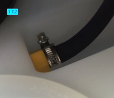
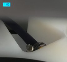
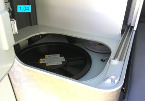
Once you're ‘in’, you can see the tank outlet fitting and hose, which are inconveniently rather snug underneath an overhead local ‘ceiling’ panel (
p1.02,03,04).
You don’t actually need to disconnect the feed hose from the tank to the sink, and I would suggest that you don’t, as I broke my yellow right-angle fitting (
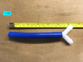
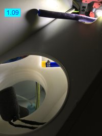
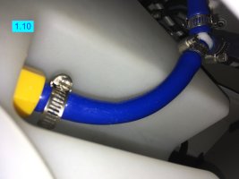
p0.7) at the tank exit while trying to remove the hose! Instead I would create a stub hose of ca. 135mm length in situ (
p1.08,09,10) by making a clean diametral cut further down the EXISTING hose, into which you will then fit the T-piece (actually a
Y-piece), in so doing bifurcating the supply to go both forward to the sink, and rearward to the shower.
(as you can see, I used my new hose to create the 135mm stub, and then attached the shortened sink hose to it, and ran new hose to the shower. But it’s better is to do as indicated above, since the OE hose is very stiff, so everything then lays a bit more easily and with less rink of kinking the new hose (softer). By the time I appreciated this it was too late, as I’d already disconnected and cut the original sink hose too short!)
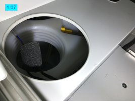
If for whatever reason you do decide to remove the pipe from the tank outlet (
p1.07), I suggest getting the hose good and warm first with a hairdryer, and make dead sure to pull it absolutely on-axis (to release the hose clip I used a small 1/4” drive ratchet and socket, which is far better than a screwdriver, depending on orientation and access).
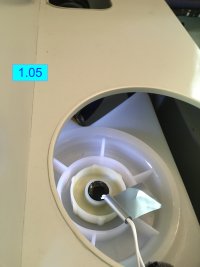
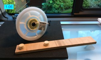
(if you break your yellow fitting, you will have to go inside the water tank (
p1.05) to swap out with a new fitting, for which you will need a peg spanner (
p1.06) which I made here:
https://vwcaliforniaclub.com/threads/oem-t6-1-rear-shower-system.44966/page-2#post-58503)
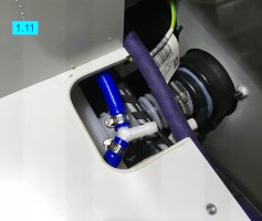
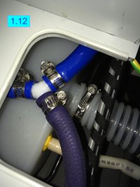
Now prefit a hose clip for the base leg of the Y-piece where you ’terminated the 135mm hose stub (
p1.11,12), and orient it such that you can tighten it - warm the hose and use vaseline to help the Y-piece engage if necessary.
Then reconnect the long hose running to the sink, shortening the sink side of the hose if necessary (depends on the detail of the pipe run) by roughly the length lost from the presence of the T-piece (
p1.11,12).
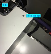
There is also a hose clamp (
p1.13) restraining / guiding the original hose run, which I released and reoriented to suit my installation - it’s a bit of a fiddle to get to it from underneath, but again I used a small 1/4” drive ratchet and socket rather than a screwdriver. I would suggest releasing this but then leave resetting it until you have got the rest of the hose run fully sorted.
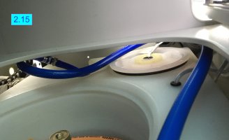
Finally, fit another hose clip to the aft leg of the Y-piece and run the whole length (1m in my case) of new 10mm bore hose towards the rear bulkhead (
p2.15) where the shower bulkhead fitting will be mounted.
You can sort out the route for this hose later when you see how it lies best (mine is gently curved around, but avoiding, the gas bottle aperture, so as not to kink nor get in the way of anything else).
2. Instal shower bulkhead fitting on NSR cupboard face & connect plumbing
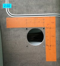
I spent ages measuring and marking out the position for the fitting (
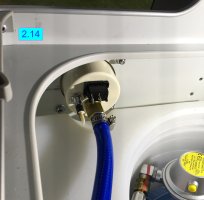
p2.02) to make sure the inside face of it was perfectly central and snug to the scallop in the water tank (
p2.14), which I presume is there to give clearance to the shower feed hose and fitting if installed.
I recommend you start with the same caution, but if you just want to ‘go for it’, then my dimension summary photo should be reliable enough!
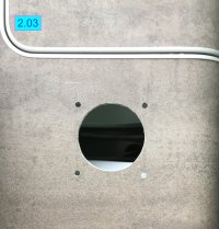
Once I’d marked out the main hole and the 4 fixing holes I drilled a 2mm pilot hole for the main hole to double check alignment on the back side.
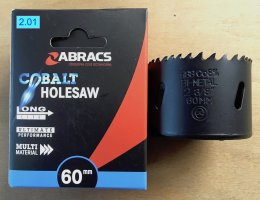
I then cut the main hole with a 60mm hole-saw (
p2.01) - NOT a nice process, but if you go very steadily you can still make a nice clean cut. I packed the back side with blue paper so as not to fill the rear cupboard cavity with swarf and dust.
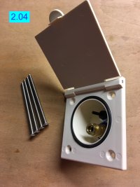
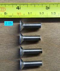
Then drill the 4x fixing holes. I already had some stainless M5 countersunk Allen screws, and so all I had to do was to cut these to length (
p2.04,05).
I used a simple washer and flat M5 ‘nyloc’ nut on the back side - admittedly slightly fiddly to offer up and get started - rather than riv-nuts, as I didn’t want to trust the honeycomb sandwich panel to take the screw-tightening torque.
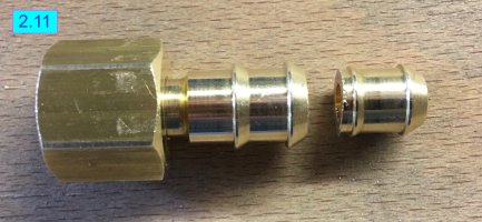
I shortened the brass hose stub (
p2.11) on the back of the shower bulkhead fitting, as there is an initial small-diameter ‘fir-tree’ section which does not help to grip this size of hose, and so a shorter stub meant more clearance to the tank scallop and an earlier curve in the hose.
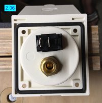
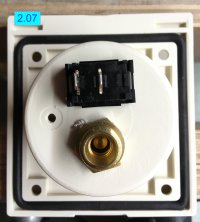
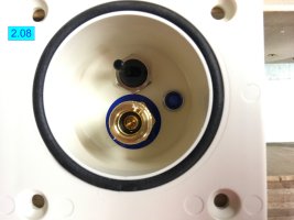
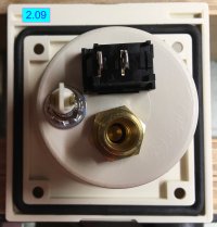
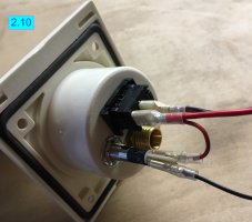
Even though the OE system on the van I rented last summer had no telltale LED indicating pump-on, I decided that I’d fit one, per comments on other people’s shower installation threads, so I drilled for this and installed it (
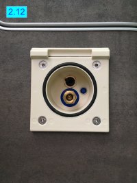
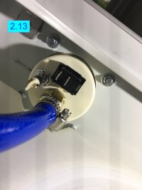
p2.06,07,08,09,10) before finally fixing the bulkhead fitting into place (
p2.12,13,14,15).
3. Connect shower switch to sink tap switch
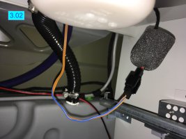
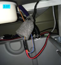
If you fish around under the galley sink at its forward end, you will find a connector to the sink tap microswitch wrapped in a little foam jacket (
p3.02).
Unwrap this so that you can unmake the connection.
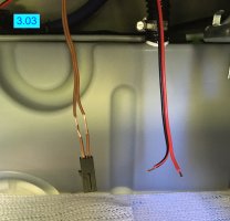
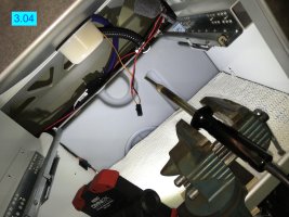
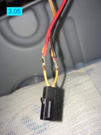
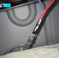
All you need to do now is to run a 2-core cable (I had some light speaker cable which is plenty heavy enough) from the switch on your new shower bulkhead fitting to the under-sink space, and splice it into the sink microswitch switch 2-core cable (
p3.03,04,05,06,07).
The route should be tucked against the body side panel alongside the main electrical harness.
The sink tap switch, and therefore the newly-fitted shower switch, do not supply +12V to the water pump in the tank; instead they rather
earth the switch line which, thanks to the way the pump is electrically configured, then energises it so that it runs. All you are doing above is connecting the shower switch in parallel with the sink switch, so that whichever switch is thrown, the pump will run.
[CORRECTION 18-Aug-22] I set my shower switch body with such an orientation as to ensure that the shower runs when the switch lever is thrown towards car centreline - this made most sense for my logic!
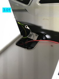
Due I think to the 'earth-dragging’ nature of the pump switch function, and my initial false expectation that I was simply connecting a positive and an earth (
p3.01) to the LED, I was not able to get the LED to light other than in the exact reverse of what is useful! So, I could make it light whenever the shower was off, and vice versa. In the end I ran out of time before departing on a month-long trip, so decided that the noise of the running pump was a good enough indicator / ‘tell-tale’ for me, and I have left it for investigation another time. I will update this guide when I get it working as it should do!
[UPDATE 18-Aug-22] I have resolved the issue with the LED and it is now working properly. There were two issues:
i) the LED had a fractured leg inside it, so I have repaired it and asked the seller to replace it for me
ii) my wiring to the LED was wrong - here is what you need to do to get a working tell-tale LED:
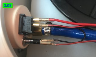
a) run the 2-core cable back from the sink microswitch, and connect one core to each of the shower switch 1/4" blades
b) put a multimeter (or test bulb) on each switch blade in turn; one will be at 0V and one at ca. 12V - note which one is at 12V
c) run a bridge from the 12V switch blade identified in b) above to one of the blades on the LED
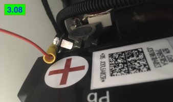
d) supply the other blade of the LED with a 12V line taken from a convenient supply (p3.08) - I used a couple of exposed threads on a clamp on the leisure battery positive post (p3.09) under the wardrobe to attach a flat U-blade connector, and thus supply this feed.
See new photos p3.08 & p3.09 appended at the end of section V for reference.
I am assuming that anyone undertaking this job is confident to strip / bare electrical wires, crimp and solder, sheath and insulate their cable and connectors? - if not, best to look up a basic electrical tutorial than me try to write one here!
OK, I think that’s about it - I hope this is useful to at least one or two folk!
Let me know please if there’s anything missing, or if you have questions?
Best of luck, and let me know how you get on! Thanks; John.
