Buy all your VW California Accessories at the Club Shop Visit Shop

Solar install on a T6.1 California Ocean ...

  • Thread starter California_Ocean
  • Start date
California_Ocean

California_Ocean

VIP Member
Messages
226
Location
Germany
Vehicle
T6.1 Ocean 204 4 motion
Anytime your spilt charge relay engages current will flow from the batteries at a higher state of charge to the lower state of charge.

The only way to achieve what you want is to isolate the two buses, either with a smps or diode or diode like device. The diode solution will need current limiting.

[Edit] Caveat: the alternator, if operating, may complicate things.

I think your simplest solution will be remove the relay and install a smps, a B2B in forum speak. You could leave your Argofet in place and things will probably work quite well.
Unfortunately the VW system controls the isolation relay between the starter and leisure banks and it is used as part of the charging strategy when on shore power. (as well as the start/stop, recuperation and Max Charge logic)

The VW charger is attached to the leisure bank and when shore-power is detected, the relay is closed to allow starter battery charging. Not sure what the logic is, both batteries simultaneously, leisure priority, or even stop charging the starter at 80%. I don't want to mess around with the original VW wiring for fear of screwing up whatever charging strategy they run - and killing the Max Charge feature. I also can't completely remove the isolation relay or I get fault codes generated.

The Argofet arrangement seems to work very well when the van is parked up and unused, and the solar works fantastically when only charging the leisure batteries.

A simple switch for both options may be the answer.
 
Y

yossarian

VIP Member
Lifetime VIP Member
Messages
641
Location
Scotland
Vehicle
T6.1 Ocean 150
The mppt has a load output function which could be used to drive a relay when the leisure batteries are at float.

User defined algorithm no 1 is probably what you're after.

You will want to current limit the path in case an engine start occurs. But if the path is mppt - argofet - relay - starter battery no current limit necessary.

Closing the relay might lower the voltage sensed by the mppt. There is some debouncing built in but you might need to consider this . The algorithm has some hysteresis setting you can do.
 
Y

yossarian

VIP Member
Lifetime VIP Member
Messages
641
Location
Scotland
Vehicle
T6.1 Ocean 150
VICTRON said:
The load output settings be used to drive the TX pin in the VE.Direct port, which can then be used to drive a BatteryProtect, a relay or an other load-shedding device. For more information see chapter TX
 
California_Ocean

California_Ocean

VIP Member
Messages
226
Location
Germany
Vehicle
T6.1 Ocean 204 4 motion
The mppt has a load output function which could be used to drive a relay when the leisure batteries are at float.

User defined algorithm no 1 is probably what you're after.

You will want to current limit the path in case an engine start occurs. But if the path is mppt - argofet - relay - starter battery no current limit necessary.

Closing the relay might lower the voltage sensed by the mppt. There is some debouncing built in but you might need to consider this . The algorithm has some hysteresis setting you can do.
I've snookered myself by using the VE.Direct port to run a Victron MPPT Display.
I think the solution is to use a MPPT with a load output and hang a trickle charger to the starter battery on it.
 
California_Ocean

California_Ocean

VIP Member
Messages
226
Location
Germany
Vehicle
T6.1 Ocean 204 4 motion
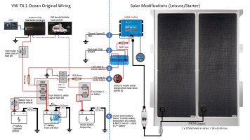
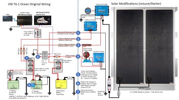
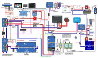
Final Solution, in the end I ended up with this ...

01_Plan.JPG
Put a switch into the feed to the starter battery and will switch it on if the van is parked up for more than a few days. The solar will then charge everything while the engine isn't running.

I also put a Vicron Smart Sense on the first leisure battery so it transmits battery temperature and voltage to the MPPT.

All seems to be working really well.

If doing it again I would use a MPPT with a proper load output and connect a good trickle charger for the starter to the MPPT load output instead of using the Argofet.

I thought making the full MPPT current available to the starter battery would be a good idea, I didn't realise it would cause the smart alternator to cut it's output.
 

Similar threads

Top