What’s behind the panels in a GC electrical cupboard?

You need to come in at the consumer unit, and the easiest way I can think to do this is to find the external sockets cabling and split it to add another entry point with a socket of some sort.

Perhaps you could let us know your experience in this area. I'm not an electrician, but it sounds like you're spit-balling ideas that have no bearing on reality and worse still could seriously damage owners vans, but I'm not a qualified electrician, so if you are feel free to tell me I'm incorrect!
@soppelsa
Sounds like you need an electrician to do this safely.
As @dominichayhoe suggests the simplest method would be to splice a cable into the back of the existing 240v electrical inlet & add a further inlet like the one below (£18 on amazon) inside the van, you could then use all your existing hook up cables etc. The supply would be coming into the normal van feed & there's no danger of any live plugs.
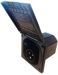
inlet.jpeg
 
@soppelsa
Sounds like you need an electrician to do this safely.
As @dominichayhoe suggests the simplest method would be to splice a cable into the back of the existing 240v electrical inlet & add a further inlet like the one below (£18 on amazon) inside the van, you could then use all your existing hook up cables etc. The supply would be coming into the normal van feed & there's no danger of any live plugs.

View attachment 89228
Agreed, with one small addendum, that is I'd put this socket in the electrics cupboard as my Jackery sits nicely in there too!

I'm sorry to say I think an electrician would likely respond with 'You're trying to do what?'!!!! To Soppelsa's comments. But I could be wrong ;)
 
I'm sorry to say I think an electrician would likely respond with 'You're trying to do what?'!!!! To Soppelsa's comments. But I could be wrong ;)

Its the sort of thing that I would happily do myself.

I was trying to politely suggest that it doesn't sound like Soppelsa should be let loose with a screwdriver.
 
I just presumed the rear 240v sockets would be fused and all other circuits be fused accordingly.
I did not know that 240v had polarity issues ,once you connect live to live and neutral to neutral current can flow anyway.
After all its AC alternating current. I cant see the difference between the external shore socket and the internal 13a socket apart from the shore is on the other side of an isolator.
I must admit feeding it the way I said is and not recommended and dodgy but installing an input by splicing into the wiring harness might invalidate the warranty.
I also presume the the yeti 240v output is fused.
I cant see a problem connecting 12v to the rear 12vdc 20a socket.
What do you do when you jump start a car. you put 2 x 12vdc supplies in parallel, normally you get a discharge from the good battery to the flat one until they are equal.
Only trying to help.
 
I must admit feeding it the way I said is and not recommended and dodgy but installing an input by splicing into the wiring harness might invalidate the warranty.
I also presume the the yeti 240v output is fused.
Its the idea of having a lead with a live plug on it thats setting the alarm bells ringing, its one of those things that you never, ever , not in a million years do. Its worse than using a large nail to replace a blown fuse.

A competent electrician should be able to wire in a new electrical inlet in a way that is totally reversible. If it needed removing for warranty purposes.


I cant see a problem connecting 12v to the rear 12vdc 20a socket.
What do you do when you jump start a car. you put 2 x 12vdc supplies in parallel, normally you get a discharge from the good battery to the flat one until they are equal.
This sounds more logical & sensible, I am not sure what effect it would have on the battery monitoring.

The most effective simple, upgrade I have seen is someone has replaced the big red isolator switch with a multi position one & added a further normal matched leisure battery wired into this. Its doubled the battery capacity, retained all the existing charging infrastructure, & only cost about £200 in total.
 
Its the idea of having a lead with a live plug on it thats setting the alarm bells ringing, its one of those things that you never, ever , not in a million years do. Its worse than using a large nail to replace a blown fuse.

A competent electrician should be able to wire in a new electrical inlet in a way that is totally reversible. If it needed removing for warranty purposes.


This sounds more logical & sensible, I am not sure what effect it would have on the battery monitoring.

The most effective simple, upgrade I have seen is someone has replaced the big red isolator switch with a multi position one & added a further normal matched leisure battery wired into this. Its doubled the battery capacity, retained all the existing charging infrastructure, & only cost about £200 in total.
Your absolutely right, don't know what I was thinking of.
A lead with a live plug is a definate no no.
It should not be attempted at any cost.
Just going through the scinarioes in my head {what if somebody caught the cable and pulled the plug out}
What a dope I am.
I was
 
I just presumed the rear 240v sockets would be fused and all other circuits be fused accordingly.
I did not know that 240v had polarity issues ,once you connect live to live and neutral to neutral current can flow anyway.
After all its AC alternating current. I cant see the difference between the external shore socket and the internal 13a socket apart from the shore is on the other side of an isolator.
I must admit feeding it the way I said is and not recommended and dodgy but installing an input by splicing into the wiring harness might invalidate the warranty.
I also presume the the yeti 240v output is fused.
I cant see a problem connecting 12v to the rear 12vdc 20a socket.
What do you do when you jump start a car. you put 2 x 12vdc supplies in parallel, normally you get a discharge from the good battery to the flat one until they are equal.
Only trying to help.
The main problem for me is I have not seen an electrical circuit diagram of the entire vans wiring, therefore if you try and do anything with your electric circuit it wasn't intended for, you may think you are simply sending energy one way down a wire, but you have no idea if there are other components that will be affected, or that it will go where you think it's going to.

The word 'current' should give you an idea. Electrical current will find its easiest route possible, like water and gravity. Not necessarily the one you intended!

You could very easily cook components.

Jump starting a car is quite different as it is a one off, and I'd imagine also not recommended by the manufacturer!

Also if you put 240v of current in at your 3 pin plug, the consumer unit is at the end of the chain rather than the beginning, so doesn't get the chance to isolate any overloads or surges.
 
Last edited:
Your absolutely right, don't know what I was thinking of.
A lead with a live plug is a definate no no.
It should not be attempted at any cost.
Just going through the scinarioes in my head {what if somebody caught the cable and pulled the plug out}
What a dope I am.
 
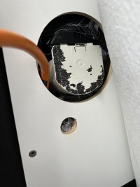
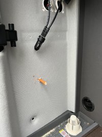
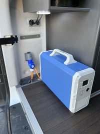
My solution for supplying mains when main leisure battery gets low or when we need to use sockets of grid, simply remove back panel the mains socket is just behind simply add to external socket, this way it keeps all the consumer units doing what they should keeping the electrics safe.

IMG_3179.JPG

IMG_3181.JPG

IMG_3185.JPG
 
My solution for supplying mains when main leisure battery gets low or when we need to use sockets of grid, simply remove back panel the mains socket is just behind simply add to external socket, this way it keeps all the consumer units doing what they should keeping the electrics safe.

View attachment 89231

View attachment 89232

View attachment 89233
Luckily my Jackery will go inside my electrics cupboard so I’m going to wire the socket there as it’s then easier to plug in when the bed is down.
 
Just wanted to thank you all for the LIVEly (ho ho, sorry couldn’t resist!) discussion - this has touched on all the topics I hoped it would and all very useful info. On the 12v 20a charging question I don’t believe we have a definitive answer due to a lack of understanding of the wiring and protection in the circuits - If anyone is able / capable in rising to answering this definitively I’m sure it will be widely appreciated but until then, we’ll all continue to exercise extreme caution!

Kr

Andy
 
My solution for supplying mains when main leisure battery gets low or when we need to use sockets of grid, simply remove back panel the mains socket is just behind simply add to external socket, this way it keeps all the consumer units doing what they should keeping the electrics safe.

View attachment 89231

View attachment 89232

View attachment 89233
Thank you and massive kudos to @markicp for the inspiration and indeed the info to allow me to follow suit.

I spent a while exploring upgrade solutions and have plumbed at least initially for a lithium generator and additional AGM battery install rather than a full on second circuit installation (in a few weeks I’ll provide the full details of my experience and the pros and cons but it’s too early to say whether I’ve done the best thing for my requirements and I still have a part of the install to complete).

By way of background my wife and I both run among other things (!) hefty laptops when working full time while living off-grid with the kids on school holidays, so…

In Part I upgraded the solar controller to a Victron one so I have A) Bluetooth monitoring which is fab; B) prep’d for wider Victron installation in Part III.

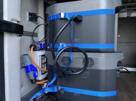
In Part II I have added an ecoflow delta max solution with additional battery. I went for an expanded version of @markicp solution above with a mains charge socket, a generator input socket and a mains-generator transfer switch as per the photo below:

27EDA559-D269-482E-9DE2-CED8BA1259C6.jpeg

The above seems to work well for providing mains power off-grid. I have additional solar panels for it and can charge it (albeit slowly on the move from the 20A dc car output socket above it) and by switching off middle RCD in the consumer unit can enable/disable charging of the AGM batteries via the generator’s inverter.

In Part III I’m adding a Victron Deep Cycle AGM leisure battery that will become the primary with the original one as backup / emergency / removed - more on this in a few weeks!
 
Thank you and massive kudos to @markicp for the inspiration and indeed the info to allow me to follow suit.

I spent a while exploring upgrade solutions and have plumbed at least initially for a lithium generator and additional AGM battery install rather than a full on second circuit installation (in a few weeks I’ll provide the full details of my experience and the pros and cons but it’s too early to say whether I’ve done the best thing for my requirements and I still have a part of the install to complete).

By way of background my wife and I both run among other things (!) hefty laptops when working full time while living off-grid with the kids on school holidays, so…

In Part I upgraded the solar controller to a Victron one so I have A) Bluetooth monitoring which is fab; B) prep’d for wider Victron installation in Part III.

In Part II I have added an ecoflow delta max solution with additional battery. I went for an expanded version of @markicp solution above with a mains charge socket, a generator input socket and a mains-generator transfer switch as per the photo below:

View attachment 90335

The above seems to work well for providing mains power off-grid. I have additional solar panels for it and can charge it (albeit slowly on the move from the 20A dc car output socket above it) and by switching off middle RCD in the consumer unit can enable/disable charging of the AGM batteries via the generator’s inverter.

In Part III I’m adding a Victron Deep Cycle AGM leisure battery that will become the primary with the original one as backup / emergency / removed - more on this in a few weeks!
Hi @andy_c thanks for sharing, look forward to more information as you build this up.
How have you wired this to enable you to “switch” to charging the agm battery?

Also, how are you getting on with the eco flow units, I’ve been looking at these, but hesitated due to the very fast charging, whilst this is attractive I’ve read that if you can’t supply enough power from mains then it won’t charge at all. Thinking of a campsite hookup which might only be 10amps for example, not sure this would be enough to charge the delta units? Also understand they are quite noisy whilst charging, what is your experience here?

Many thanks for sharing, and sorry for the questions but looking at options for power when off grid too.
 
Hi @Mr T

I can only answer half your question wrt wiring but will be more qualified to answer the “general how are you getting on and 10A” question after our trip to France over Easter hols.

I followed the pics of @markicp to encourage me to take off the panel , open up the foam and expose the wires from the external hookup point. This has an inline connector. I replaced the inline connector on the lead out of the filler with an inline splitter and took one to the industrial connector for charging the generator and the other line to the mains in on the gen transfer switch. The line that originally went from the external filler to the consumer unit now gets wired into the load out on the gen transfer switch. The generator in on the transfer switch is fed off the other industrial connector which is fed from a 3 pin output socket on the generator.

I have young children so was careful to do the above to ensure the right connectors and leads were being used that don’t expose live pins that could be dangerous - for example the industrial connectors are not the same the mains supply is female and the gen in is an industrial male. The transfer switch is IMHO important too.

One uses the gen transfer switch to switch between mains in and generator in. In this way I’m faking the external mains supply. As a result this will power the 3 pin sockets (note - as if they were an extension lead) and also charge the leisure batteries. Now I don’t necessarily want to charge the leisure batteries like this as I’m beefing up the solar capability so I can turn the middle switch on the consumer unit off which disabled the charging system (from what I can tell :).

I was going to elaborate on this on a later post but have gone this route because many installers whilst potentially willing to do a more comprehensive install haven’t really worked on or understood the GC system and are really wary of the warranty invalidation. I’m gambling my mods are mild enough not to invalidate the warranty and if they are, well then shame on VW for providing such a shonky under-spec’d system in the first place!

Does that help and answer your question, first half at least?

Kr

Andy
PS forgot to mention you can vary the charge speed of the delta max on the unit (xboost) and more fine grained from the eco flow app. So I _think_ all will be ok, but let’s see :)
 
PS forgot to mention you can vary the charge speed of the delta max on the unit (xboost) and more fine grained from the eco flow app. So I _think_ all will be ok, but let’s see :)
Thanks for taking the time to reply. I understand the splitting of the hookup input, that’s clear and easy, just misunderstood how you might stop charging the leisure battery (by choice) when running from the delta units. I will continue my research and look forward to reading about your further developments and experiences. Many thanks, I’ll take a look at the app for these units and see what is possible.
 
@andy_c Ive just realised the app isn’t available with the smaller delta units, hence why during my research I did not come across it.
 
I haven't read this thread in detail but I thought it's worth noting that you cannot connect both your onboard ac and a live hook-up ac together.
I would have thought that it would be sensible to wire in an isolator switch to ensure this can't happen - rather than a direct parallel connection as mentioned above.
Unless of course you like big blue flashes

Sent from my SM-G986B using Tapatalk

I read the bit..... " I have young children so was careful to do the above to ensure the right connectors and leads were being used that don’t expose live pins that could be dangerous - for example the industrial connectors are not the same the mains supply is female and the gen in is an industrial male. The transfer switch is IMHO important too.

One uses the gen transfer switch to switch between mains in and generator in"

.....to mean that there is a switch that prevents 2 live feeds being selected at the same time. I also took it to mean that if that is the case , the pins on the external hookup are not live when the internal source is used & vice versa.
@mpill990 - Please read in detail and perhaps post your concern? @andyinluton, thank you for reading in detail!
 
I think @mpill990 makes a good point and some of the earlier posts do look like the suggestion was to simply split the in coming wiring from the back of the hookup which would be a concern, however what @andy_c has stated is not this, but very clearly explains the route his newly wired hookup takes, and it makes sense and seems well considered from a safety aspect.
 
My intention is not to hijack the thread as overall it is very informative.
My point is simple - if you connect two ac supplies in parallel they will be out of phase. Which is effectively a short circuit - not recommended even with circuit breaker protection

Sent from my SM-G986B using Tapatalk
 
As mentioned if you fit switching to prevent a parallel connection then all good. But I can imagine some bright spark diy'er missing this out leading to more bright sparks

Sent from my SM-G986B using Tapatalk
 
My solution for supplying mains when main leisure battery gets low or when we need to use sockets of grid, simply remove back panel the mains socket is just behind simply add to external socket, this way it keeps all the consumer units doing what they should keeping the electrics safe.

View attachment 89231

View attachment 89232

View attachment 89233
Please tell me you've now also added a two way switch to this install, otherwise when you turn on your power unit, you make the outside socket live too!
 
Back
Top