2nd AGM leisure battery in the back of the Grand California

@dominichayhoe
As this is about the 12v side of things it has nothing to do with the consumer unit - that is for the 240v supply.

"this switch may not ensure the 2nd battery's current goes to the isolator area first." not sure what you mean, the switch is the isolator.

"that 2nd battery wire from the switch looks a lot thinner than the main battery". Thats not a photo of my van, so am not 100% sure, but to me it looks like the same size cables have been used for the 2nd battery as were used by the factory on the first.
I would suspect the thicker wire is to avoid a voltage drop over the long route from the engine bay to the isolator switch, whereas the thiner wire is going a matter of a few inches from the isolator to the distribution board.
The reason I mention this is because, even with my red switch turned off my over cabinet lights still work!

Not what I expected, so it makes me question how the battery is actually wired in!
 
The reason I mention this is because, even with my red switch turned off my over cabinet lights still work!

Not what I expected, so it makes me question how the battery is actually wired in!
2nd battery, Jackery, double pole marine switch, GERMAN.
I can remember when all you had was a Morrison’s carrier hung out of the caravan window, if you were lucky you went ‘wild’ camping got your keep net out and put it in the stream.
Please note in the spirit of levelling up no dialect was used in this post.
 
The reason I mention this is because, even with my red switch turned off my over cabinet lights still work!

Not what I expected, so it makes me question how the battery is actually wired in!
The lighting system has various other connections that bypass the isolator switch.

The German forum + Google translate is much more active re the Grand Cali than here, there are 360+ GC users on there, some of whom have got to grips with the electrics.
 
You are making it too complicated. There is the "big Red switch" in the electrical cupboard at the back of the van, its the isolator for all habitation electrics. for a few quid there is an off the shelf replacement for the isolator that is designed to connect more than one supply, swap the switch & there is room in the cupboard for an additional battery so only short leads required.
Half hour to install & totally reversible.
Pics below original single battery switch V 2 battery switch.
Its top left of each picture View attachment 89256
View attachment 89255
Hi Folks,

Is there anyone here who has actually placed a second battery in the cupboard? Changing the isolator switch to one which supports a second battery is definitely trivial, but has anyone got a suggestion on the best place to wire the negative terminal for the second battery into?

Many thanks!

Kr

Andy
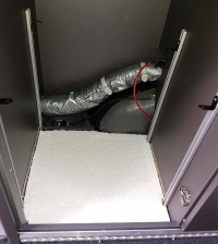
I’ve looked at this and the guy on the German forum who has posted how to do this uses the “lashing point” fixture which is found just behind the wheel arch in the cupboard.
Picture here, under the silver pipe, left of the picture.

0FA1736A-AB63-4EA8-BCAC-07C72F2C94FF.png
 
I’ve looked at this and the guy on the German forum who has posted how to do this uses the “lashing point” fixture which is found just behind the wheel arch in the cupboard.
Picture here, under the silver pipe, left of the picture.

View attachment 90364
Thanks very much @Mr T! Sorry to ask for further elaboration, but I assume you mean he’s fitted his own connection to the wheel arch - there is indeed a flat plate that I can fee on the arch that I guess he’s drilled into?

Many thanks!

Kr

Andy
 
Thanks very much @Mr T! Sorry to ask for further elaboration, but I assume you mean he’s fitted his own connection to the wheel arch - there is indeed a flat plate that I can fee on the arch that I guess he’s drilled into?

Many thanks!

Kr

Andy
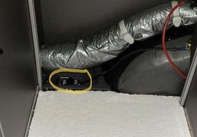
No, not on the wheel arch, that’s just where the cable is currently resting. It’s bolted here (circled in yellow) zoom in the pic and you’ll see.

929D81C1-46FF-496B-9E98-63824E6FD0A7.jpeg
 
No, not on the wheel arch, that’s just where the cable is currently resting. It’s bolted here (circled in yellow) zoom in the pic and you’ll see.

View attachment 90366
Awesome @Mr T - thank you so much! Had a proxy lost in translation moment - our German friend actually meant the actual lashing point

Thanks for the response - appreciate it!
 
Awesome @Mr T - thank you so much! Had a proxy lost in translation moment - our German friend actually meant the actual lashing point

Thanks for the response - appreciate it!
Let us know how you get on, I’m still waiting for my GC but improving the electrics is a requirement, not for any epic off grid adventures, just want to go 3 or 4 days without worrying about being on hook up. Even then, I’m not too bothered about 240v whilst “off-grid” just want to be able to operate all the 12v stuff with no fear of running out of power.
 
You are making it too complicated. There is the "big Red switch" in the electrical cupboard at the back of the van, its the isolator for all habitation electrics. for a few quid there is an off the shelf replacement for the isolator that is designed to connect more than one supply, swap the switch & there is room in the cupboard for an additional battery so only short leads required.
Half hour to install & totally reversible.
Pics below original single battery switch V 2 battery switch.
Its top left of each picture View attachment 89256
View attachment 89255
hi andyinluton

where have you sited the second leisure battery?...do you have any photos to post?

do you have a "wiring diagram" of the set up to post...fuse ratings, cable ratings etc..will the solar panel charge the second leisure battery??

This seems a very smart simple solution.

Regards

Lee
Hi Lee, I don’t believe Andy has done this, the information being discussed in this thread can be found here on the German forum

https://www.caliboard.de/topic/2592...e-im-stauschrank/?tab=comments#comment-355191
 
Hi Lee, I don’t believe Andy has done this, the information being discussed in this thread can be found here on the German forum

https://www.caliboard.de/topic/2592...e-im-stauschrank/?tab=comments#comment-355191
That’s correct, I’ve just being doing the research so far.

The solar panel etc will work exactly as before.

I also got the quote through yesterday for all the parts from the OEM supplier to retrofit an original solar panel along with details of further roof panels to increase the capacity.
 
That’s correct, I’ve just being doing the research so far.

The solar panel etc will work exactly as before.

I also got the quote through yesterday for all the parts from the OEM supplier to retrofit an original solar panel along with details of further roof panels to increase the capacity.
Hi Andy, very interested in hearing about the additional panels. How much extra can be added alongside the standard panel? Also is this a uk source?
Thanks in advance.
 
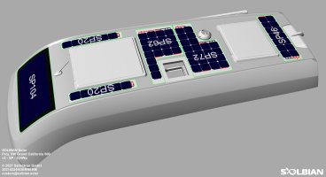
Quote & contact details for retrofit below.

Image shows additional possible panels to bring up the capacity.


Thank you for your enquiry and interest in our products. Please excuse the delayed answer, we are receiving an extremely high number of requests at the moment.

We manufacture the original solar panels for the Grand California and have permission from VW to supply these identically - except for the connector and the VW label - to you as the end customer. It would also be possible to mount additional modules with up to 220Wp on top of the roof - enclosed you find a rendering with possible modules (depending on the configuration on the roof).

Here are the system costs (104Wp Grand California 600):

SolbianFlex custom VW GC600
€ 1126,68

Pre-mounted adhesive
€ 37,00

Victron SmartSolar 75/15
€ 120,00

Shipping EU
€ 12,90


TOTAL
incl. VAT
€ 1296,58


excl. VAT
€ 1080,48

…shipping to the UK is 80€.

There are no specific installation instructions for the VW module, but as the cables have already been placed here is some information:
- Enclosed you will find a picture showing the cable assignment on the original charge controller - the Victron controller is to be connected in exactly the same way. From the roof (the cover is fixed with Velcro) there should be cables in red (+) and black (-), these are connected to the PV connection. From the fuse block should come red with a white stripe (+) and brown (-), these cables are connected to the BATT connection. Unfortunately, we cannot guarantee that the cables have already been laid in your vehicle and that the cable colours correspond to this assignment, but so far this seems to be the case with all vehicles.
- Apart from our material, you only need tools and sealant for the joint around the module (Sikaflex 295-UV, see below).

Here is some more information about the installation:

Installation (2 people recommended):
Solar cells are relatively sensitive as long as they are not yet glued - handle them as carefully as possible and do not bend them too much.
1) Cut the protective film on the back in the area of the cables so that you can easily pull it off without getting caught on the cables.
2) Place the module on top and mark the cable positions. Then drill holes for the cables - we recommend a rectangular cut-out slightly larger than the cable foot with a multitool or jigsaw.
3) Clean the surface thoroughly, e.g. with acetone - it must be clean and free of grease.
4) Place the module on top and fix the half without cables with tape so that they can no longer slip.
5) Lift the module on the side of the cables, fold back the first 10cm of the protective film on the back and press the edge (approx. 1cm, not more!) of the module onto the roof. The tape can now be removed and the module can no longer slip.
6) While one person carefully lifts the module (the cells must not be bent strongly, which is why the area with cells should not yet be pressed on in step 5), the second person slowly pulls off the protective film and meanwhile presses the module onto the roof step by step with a cloth.
7) As soon as the entire module is glued on, carefully press the entire surface again, especially the area around the cable gland and the outer edges are important here.

For caulking, we recommend Sikaflex 295-UV in combination with smoothing agent N, which works much better with this sealant than soapy water. The edges of the module and vehicle should be masked off to protect them - we usually caulk as follows:
1) mask the edges
2) Apply sealant
3) Press sealant into joint with finger and plenty of smoothing agent to prevent air pockets and gaps.
4) Peel off excess sealant with jointing tool
5) Remove tape
6) Carefully finalise joints with finger and plenty of smoothing agent, here the edges remaining from the masking tape are still smoothed out

If you have any questions during the installation, please do not hesitate to contact us by phone.

With kind regards
Michael Körner

Sailectron GmbH
Michael Körner
Geschäftsführung | Sailectron GmbH
SOLBIAN Solar DE & AT
Neufeldweg 147F/2, A-8041 Graz
DE: +49 1520 4096530
AT: +43 650 5709366
web: www.solbian.solar
email: m.koerner@solbian.solar
SOLBIAN-Solar_GC600-addon_v2-SP-324Wp.jpeg
 
I’m still perplexed by the installation of the second battery. Replacement of the isolator switch and the powering of the 12volt electrics of the van I get… But… Does anyone understand how our German friend wired the battery into the charging system both from the alternator and the 240 volt system - via the trickle charger I assume - does this break out in the electrical cupboard?
 
Try visualising it like this:

If you think of it as putting an extra battery next to the front one connected by very short cables you can probably see how that would work ?

Now stretch the cables so it reaches the back of the van - nothing has changed electrically.

Now instead of using your stretched cable just attach the rear battery to a cable that already runs from the front battery to the rear of the van.

Finally to make it easier to do the connection, fit a new switch at the connection point that is designed to take more cables.


The charging is unaffected, as nothing has changed as far as the front battery & the charging circuit are concerned, but because the two batteries are now connected if you charge one the same happens to the other the voltages on both batteries will be the same.


The only thing that isn't correct is the remains hours left displayed on the control panel, this is because the panel doesn't know you have double the amount of Amp hours fitted, it can only go by the state of charge in Volts of the battery it expects to be there.
The calculation is easy - you have twice the amount that the display shows.
If it says the battery is 80% full with 40hours run time, it means both batteries are 80% full and you have 80 hours run time available.
 
Thanks @andyinluton. I think you’re suggesting by putting the switch into the 1+2 position to achieve this and this raises the concern of charging through those cables and switch?
 
Yes that is how the charge would reach the battery.
 
Many Thanks! Ok, I had assumed he was doing something more sophisticated to avoid any of the pitfalls of doing that.

Kr

Andy
 
Many Thanks! Ok, I had assumed he was doing something more sophisticated to avoid any of the pitfalls of doing that.

Kr

Andy
What pitfalls?
 
Try visualising it like this:

If you think of it as putting an extra battery next to the front one connected by very short cables you can probably see how that would work ?

Now stretch the cables so it reaches the back of the van - nothing has changed electrically.

Now instead of using your stretched cable just attach the rear battery to a cable that already runs from the front battery to the rear of the van.

Finally to make it easier to do the connection, fit a new switch at the connection point that is designed to take more cables.


The charging is unaffected, as nothing has changed as far as the front battery & the charging circuit are concerned, but because the two batteries are now connected if you charge one the same happens to the other the voltages on both batteries will be the same.


The only thing that isn't correct is the remains hours left displayed on the control panel, this is because the panel doesn't know you have double the amount of Amp hours fitted, it can only go by the state of charge in Volts of the battery it expects to be there.
The calculation is easy - you have twice the amount that the display shows.
If it says the battery is 80% full with 40hours run time, it means both batteries are 80% full and you have 80 hours run time available.
All except the fact the cabling to your new battery was never designed to take a charge from the alternator, so no one knows if that could cause any issues.
 
All except the fact the cabling to your new battery was never designed to take a charge from the alternator, so no one knows if that could cause any issues.
What issues are you expecting? You appear to be overthinking it.

It’s no different to the ocean having a battery at the front & back.
Put a large cube fuse on the back +ve connection if you are worried about overloading anything.
 
Try visualising it like this:

If you think of it as putting an extra battery next to the front one connected by very short cables you can probably see how that would work ?

Now stretch the cables so it reaches the back of the van - nothing has changed electrically.

Now instead of using your stretched cable just attach the rear battery to a cable that already runs from the front battery to the rear of the van.

Finally to make it easier to do the connection, fit a new switch at the connection point that is designed to take more cables.


The charging is unaffected, as nothing has changed as far as the front battery & the charging circuit are concerned, but because the two batteries are now connected if you charge one the same happens to the other the voltages on both batteries will be the same.


The only thing that isn't correct is the remains hours left displayed on the control panel, this is because the panel doesn't know you have double the amount of Amp hours fitted, it can only go by the state of charge in Volts of the battery it expects to be there.
The calculation is easy - you have twice the amount that the display shows.
If it says the battery is 80% full with 40hours run time, it means both batteries are 80% full and you have 80 hours run time available.
Admittedly i haven't looked (currently away from van), but do you happen to know if the negative cable from the engine bay mounted leisure battery (who thought that was a good isea?!) runs all the way back to the "electrics" cupboard?...or is it bolted locally to the frame of the vehicle within the engine bay? Clearly mounting the second battery in parallel if directly connected to pos and neg of existing battery is the most secure of options.
 
No it’s connected to vehicle chassis. For rear battery there is a tie down point that can be used to bolt the -ve from the rear battery to.
 

VW California Club

Back
Top