Buy all your VW California Accessories at the Club Shop Visit Shop

How-To install DC-DC charger to replace VW Split Charge relay

Loz

Loz

Super Poster
Lifetime VIP Member
Messages
5,590
Location
Berkeley Gloucestershire
Vehicle
Cali now sold
This guide takes you step by step through fitting the Travelvolts DC-DC charging kit for California leisure battery charging.

Why fit this kit:
VW are still installing their standard split charge relay on vehicles fitted with leisure batteries, however, the latest Bluemotion technology has a few undesirable side effects with leisure battery systems.
In order to leave headroom in the starter battery for the surge in regenerative braking the alternator will stop charging when the starter battery when it reaches about 80%, also to improve economy the alternator will at times just idle and not perform any charging.
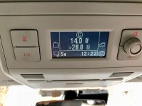
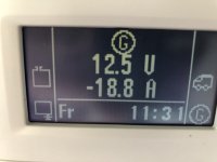
This can cause current to flow back from the leisure batteries to the starter battery as seen here on the california control panel.
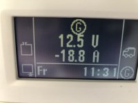
IMG_0056.jpg

Step 1, Disconnect rear second battery:
These instructions refer to the twin leisure batteries in the California you may not have the second battery.
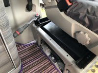
First open the panel at the bottom the rear wardrobe to reveal the second battery if fitted.
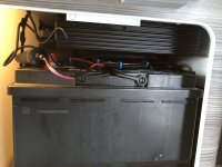
IMG_0065.jpg

Unbolt the retaining clamp (13mm socket).
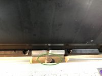
IMG_0064.jpg

Use a large flat screwdriver or trim tool to lever up the battery to get it over the edge of the opening
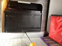
IMG_0066.jpg

Now carefully slide out onto the boot floor.
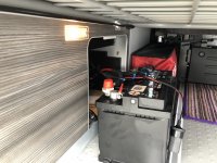
IMG_0067.jpg

Disconnect the negative terminal (10mm Socket)
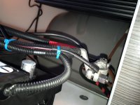
IMG_0068.jpg
 
Last edited:
Step 2, Remove passenger seat:
Slide the passenger seat forwards and backwards to reveal the 4 bolts holding the seat to the base.
IMG_0069.jpg IMG_0070.jpg

Unbolt the 4 bolts and tilt the seat up to reveal the plugs under the seat.
IMG_0072.jpg

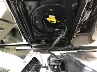
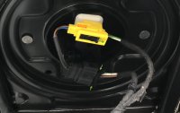
Slide the black safety catch to allow you to push the yellow catch and release the airbag plug and squeeze the side tabs to release the black heated seat plug (if fitted).
IMG_0072 copy.jpg

Now remove the passenger seat.

Continue to step 3.
 
Last edited:
Step 3, Disconnect Starter and leisure battery

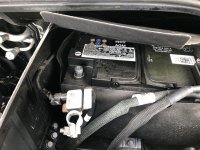
Remove the negative clamp from the starter battery.
IMG_0077.jpg

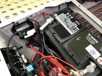
Remove the Leisure battery rubber cover.
IMG_0073.jpg

Remove the negative and then positive clamps of the leisure battery.
IMG_0074.jpg

Remove the trim at the back of the passenger seat base
Remove the clamp for the leisure battery.
IMG_0070a.png
Disconnect the vent pipe from the negative end of the battery and lift out the leisure battery.

Continue to step 4.
 
Last edited:
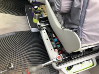
Step 4, Remove factory split charge relay.
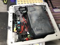
Remove the 2 screws holding the relay to the mounting plate and the 2 screws holding the mounting plate to the seat base.
IMG_0074a.png

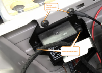
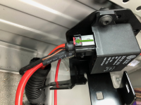
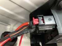
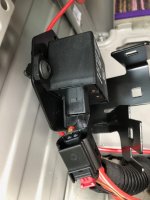
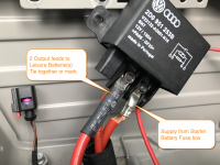
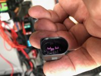
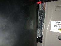
Discard the bracket and lift up the relay so you can unplug the control plug by pulling out the red slide and then pinching the sides of the plug to remove it.
IMG_0080a.png IMG_0081.jpg IMG_0082.jpg

Take note or mark the supply cables at the bottom of the relay.
IMG_0083a.png
Now disconnect the relay.

Continue to step 5.
 
Last edited:
Step 5, Improve the earth to the seat base

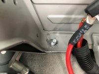
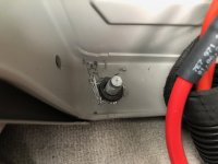
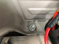
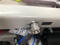
Remove the nut holding the seat base to the chassis and remove the paint around the bolt. Fit a locking washer and refit the nut and tighten.
IMG_0084.jpg IMG_0086.jpg IMG_0087.jpg

Continue to step 6.
 
Last edited:
Step 6, mount the DC DC charger and parts.

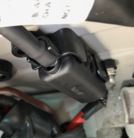
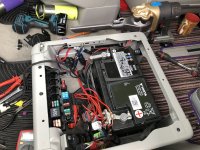
Mark holes for the charger, drill and mount the charger on the side of the seat base towards the rear.
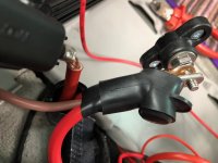
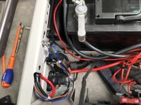
Connect the 2 leisure battery supply cables to the large power post with the Output wire from the Charger, feed all 3 cables up the sleeve of the protection cap, but leave the nut loose for the time being. This is the large brown cable on the Redarc unit.
IMG_0088.jpg

Connect the main battery supply feed to the midi fuse carrier at the end of the supply cable to the charger. This is the red cable on the Redarc unit.
IMG_0090b.png

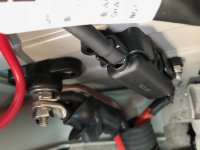
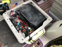
Now mark, drill and mount the power post and midi fuse carrier so that it looks like this , ensuring the main supply cable is well away from the seat base.
IMG_0090.jpg
Now tighten up the nut on the power post and slide over the rubber cap. tighten up the nuts on the midi fuse carrier. I also added some insulation tape to the battery supply cable as there was too much bare cable for my liking.

Next I fitted a bolt to the seat base to act as the earth for the charger and connected the earth cable from the charger. As the california has a battery monitor the negative must go directly to the chassis and the reason I improved the earth to the seat base earlier.
IMG_0097.jpg

Next connect the trigger wire for the charger to the relay plug we removed from the relay earlier.
IMG_0093.jpg

Tidy up and cable tie your installation.
IMG_0096.jpg

Continue to Step 7.
 
Last edited:
Step 7, refit batteries.

Replace the leisure battery into the seat base and clamp back down.
Connect the Positive clamp to the leisure battery.
Connect the vent pipe
Connect the negative to the battery.
Refit the Rubber battery cover.
IMG_0100.jpg IMG_0101.jpg IMG_0102.jpg

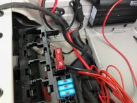
Replace the 80A fuse for the supplied 50A fuse;
IMG_0092.jpg

Now reconnect the negative to the second leisure battery and replace the rear battery reversing the instructions in step 1.

Now connect the negative to the starter battery.
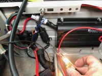
You can test you have a supply to the charger if you want to.
IMG_0099.jpg

!! Do not be tempted to test the system at this stage as your airbags are disconnected and you will generate a fault you will need cleared.

Continue to step 8.
 
Last edited:
Step 8. Testing;

Rest the passenger seat back on its base.
Tip it to one side and reconnect the yellow airbag plug and the seat heater plug (if fitted)
If you have a california ocean you will need to reset the clock on the camper display unit and then change the display to battery status.

You can now start the engine and check it is charging.
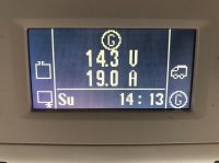
IMG_0104.jpg IMG_0105.jpg

As you can see above the charger is showing profile A and boost mode charging. The camper display unit is showing greater than 20A flowing in.

After running for 20 minutes I can see the charge rate drop.
IMG_0106.jpg

continue to step 9.
 
Last edited:
Step 9. Finishing up

Bolt the passenger seat back down.
Refit the cover trim to the rear of the passenger seat

Re-learn the auto windows that were lost whilst the battery was disconnected.

Remove sticky sweet from carpet next to passenger seat (you may not have to do this :) )

Audit your tools and any bits you have left over.

Total time taken 2 hours.

I think this is complete, any questions add below..

there is no step 10 :)
 
Last edited:
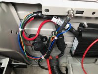
Nice job. Couldn’t help wondering if it’s not simpler to re code the blue motion bollocks to get the alternator to behave normally?
 
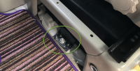
There's a chassis earthing stud under the flap in the carpet.
 
More info please. If the alternator is signing off at 80% of starter battery then that surely hampers leisure battery charging? Or does DC/DC then take charge from the starter battery to charge the leisure battery?
If this is the case then the starter battery will discharge quickly and the alternator will kick back in........
 
There's a chassis earthing stud under the flap in the carpet.
Couldn't get to it without removing the seat base and all the gubbins. I had a good rummage about but the battery negative travels off to the shunt way under the carpet somewhere.
 
Last edited:
More info please. If the alternator is signing off at 80% of starter battery then that surely hampers leisure battery charging? Or does DC/DC then take charge from the starter battery to charge the leisure battery?
If this is the case then the starter battery will discharge quickly and the alternator will kick back in........
Yes correct, you never get the full charge in the leisure batteries and this upgrade kit fixes that.

The unit is controlled by the original control cable from the relay so when start stop kicks in the charger pauses and resumes a few seconds after the engine restarts.
I am expecting the start stop to kick in later and after testing the next day and the charging current had dropped to 7 amps the start stop kicked in as usual.
 
Last edited:
I still don’t understand where the energy is coming from to support the DC/DC unit.
If the starter battery is feeding it then it will always require charging from the alternator effectively undermining the blue motion thing?

Obvs I’m missing something?
 
"A DC-DC charger is effectively a smart-charger for your 12V system. It isolates the house battery system from the alternator, so that the vehicle’s computer management system sees it as something like a set of lights. At the same time, it boosts the charge voltage at the house battery from as little as 9V back up to 14.4V (or higher, if required) to maximise charging capacity, delivering it in stepped form, like your smart mains charger, achieving close to 100 per cent charge after a day’s driving"
dc-dc-battery-chargers-explained
 
Yes but the point I’m trying to get my head around is the “no free lunch” aspect.

The charger needs to take energy from the starter battery which in turn will discharge thus forcing the alternator to kick in again thus negating the blue motion aspect.

If your alternator is running most of the time then you may as well just run a standard setup with split charge?
Yes your correct, what this stops is the back flow from the leisure side to the starter battery when the BCU is playing silly buggers with the alternator and ensures a proper charge to the leisure side.
A simple split charge allows flow in both directions etc.
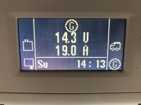
This is the non charging state..
IMG_0056.jpg

This is the new charging state;
IMG_0106.jpg
 
Ah that’s makes sense. Wouldn’t a simple diode in the leisure feed suffice?
 
Thanks for the post Loz.

Although less of an issue for non Bluemotion vans, as these should fully charge the leisure batteries, reading the link Skewif posted would indicate that older vans don't fully charge the leisure batteries either.

Maybe I should look into this too?

Alan
 
Thanks for the post Loz.

Although less of an issue for non Bluemotion vans, as these should fully charge the leisure batteries, reading the link Skewif posted would indicate that older vans don't fully charge the leisure batteries either.

Maybe I should look into this too?

Alan
Hence the need to plug in once a month for 16 hours to fully charge and avoid sulfation. These DC to DC chargers provide a 3 stage charge that is much better for lead acid batteries rather than the crude fixed voltage output from an alternator. Looks like they are vital equipment if you have BlueMotion/smart alternator.
On pre BM even though these chargers are better suited you would still need to do a very long drive (maybe 10+ hours) to get the batts truly full and where they regularly need to be. If you don't do anything like those kinds of drives it might be best sticking with what's fitted, plugging in every month and save the £200 for new batts when needed.
 
Back
Top