Installed mine now under the driver seat.
View attachment 64570
I didn't need to disconnect or remove any batteries, or disconnect any seat wiring, or remove seat bases. I undid the 4 bolts per seat. This is possible using a normal socket set by swivelling and moving the seat to get access to each nut/bolt. Then I lifted each seat off the base and tilted it backwards so that the headrest rested on the rear bench. There was enough slack on the seat wiring to do this.
I was able to push a fibreglass rod through from the passenger side and pick it up on the driver side. Then a simple matter of taping each cable to the rod and pulling back through.
I made my own relay "plug" to replace the VW relay. I got a dead relay from a local motor garage, removed the insides and soldered 1.5m of 10mm cable to the connectors. Then replaced the casing and filled up with hot melt glue. Epoxy would have been better.
I used a piece of 11mm OSB as a mount for the charger, bolted into the existing holes in the seat base. I used glue gun to lightly stick the nuts on the backside of the OSB as they are not accessible when the OSB is in place.
The grounding point is easily accessible under the driver's seat.
View attachment 64571
I fished through a few extra cables. 10mm for a future Pure Sine Wave inverter, and a power feed for a van Plex server and WiFi router.
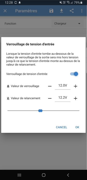
The App does not display charging current which is very annoying. It displays starter battery voltage, and only shows leisure battery voltage during charge.
I have ordered a Victron battery shunt to get a better handle on state of charge.


.jpeg")