240V in-vehicle supply - is it good? & HOW TO GET YOUR PLUG TO SIT FLAT

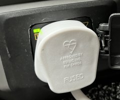
The inverter socket is some kind of multi affair - supposed to accept different plugs. But a UK 3 pin just doesn't fit well at all. I made up a small schuko extension lead and it fits perfect.


That sounds like a good option. I do use a small extension that fits better but not the Schuko one.
I may wait until Vw fit the new socket and ask them to fit it upside down :headbang and see how it goes.
 
SEE UPDATE AT BOTTOM:

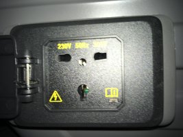
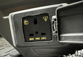
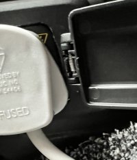
Further to my novice mains-user post in March this year, I subsequently found that the little ca. 2mm high raised ridge around the mains socket front face prevents some (probably most!) plugs from going down flat on the plate and connecting successfully to the 240V supply.

This is clearly quite a nuisance, so today I managed to get the unit off in order to dress down the offending stand-proud until it was nearly flush, tested it - all good - and reassembled it.

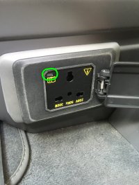
I also took the opportunity to refit the unit the 'correct' way up, so with the earth pin uppermost allowing the lead to point to the floor, which means that i) the annotation on the socket face is now upside down - who cares!, ii) the tell-tale ON-light is uppermost, so easier to see, and iii) the sprung-loaded cover now folds backwards towards the handbrake lever, so is out of the way and less vulnerable.

It was murder to get the unit out, and I had to remove the seat from its plinth to try to see what was going on, but once I got it out I realised how easy it would be to do once you knew which are the clips to spring to release the receptacle, and where they are!

You MUSTN'T remove the facia plate on the side of the seat base UNTIL you have the 3-pin receptacle out from the inside - if you try to do it in the wrong order you will almost certainly break something!

If anyone needs to do this same mod., or at least wants to get the driver base mains socket and facia plate off, give me a shout and I'll do a 'how-to'.

(NB the outline of paler grey abrasion marking at the chamfered extremity of the facia plate looks dreadful in the 2 photos below, whereas in reality it is hardly even discernible!)

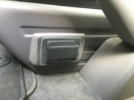
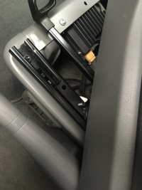
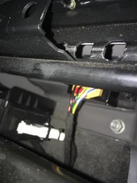
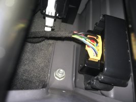
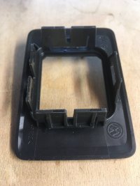
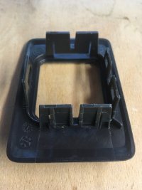
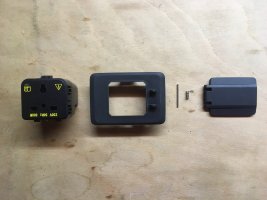
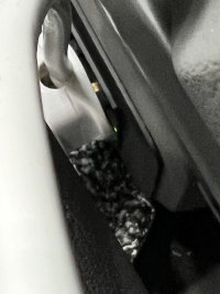
HERE BELOW THE ORIGINAL TRIO ARE 4 MORE PHOTOS SHOWING THE RECEPTACLE FOR THE MAINS SOCKET, WITH AND WITHOUT THE MAINS SOCKET CLIPPED IN - SORRY, I DIDN'T TAKE A SHOT OF THE MAINS SOCKET ON ITS OWN - I CAN GO BACK IN AND TAKE IT OUT AGAIN (NOW THAT I KNOW HOW!) IF NEED BE . . .


View attachment 100702
View attachment 100705
View attachment 100706
View attachment 100716
View attachment 100717
View attachment 100718
View attachment 100719

Evening all.

I went back and had a look at this again this afternoon, and as I suspected, now that I know how to release the 240V plug receptacle it’s dead easy to do the whole job without removing the driver’s seat.

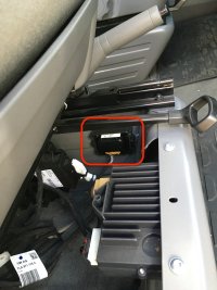
You just swivel the seat and slide it back as far as possible to expose the forward centre-side quarter of the cavity under the seat, and it’s then child’s play to disconnect the harness and release the plug receptacle.

You then have easy access to remove the fascia plate, dress down the upstand, and easily reverse the installation to receive the plug the right way up if you wish.

I’ll write the how-to storyboard tomorrow for anyone who’s still interested.

Thanks; JS.


PART I: HOW TO GET YOUR MAINS PLUG IN THE DRIVER'S SEAT 240V SOCKET TO SIT FLAT AND THE CORRECT WAY UP

SO THIS IS WHAT YOU START WITH - THE OBSTRUCTIVE PERIMETER UPSTAND STOPS THE (UPSIDE-DOWN!) PLUG FROM SEATING, VERY LIKELY EVEN FROM MAKING RELIABLE ELECTRICAL CONTACT, WHICH IS WHAT FORCED ME TO GO IN AND MODIFY IT:
26878ADE-22CE-4272-BD74-63E0AEBB0C01.jpg

AND THIS IS WHAT YOU CAN ACHIEVE INSTEAD: NO UPSTAND - PLUG RIGHT WAY UP - FLAP ORIENTATION IMPROVED - TELL-TALE 'ON' LIGHT MORE EASILY VISIBLE:
IMG_4652.JPG
IMG_4651.JPG

START BY SWIVELLING THE DRIVER'S SEAT AND SLIDING IT BACK TO GET ACCESS TO THE FWD LEFT QUARTER UNDER-SEAT SPACE:
IMG_4762.jpg

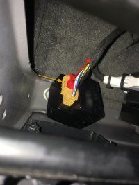
YOU NEED TO EXTRACT THE CENTRAL BLACK SHINY MAINS SOCKET (LEAVE THE CONNECTOR ATTACHED UNTIL THE MAINS UNIT IS RELEASED [NOTE IT LATCHES USING THE RED ELEMENT] ):
IMG_4765.jpg
IMG_4769.jpg

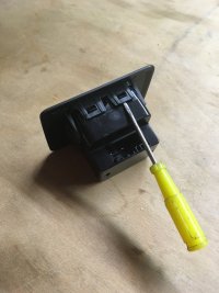
HERE IT IS ONCE REMOVED TO SHOW HOW IT IS CLIPPED TO THE FASCIA PLATE - YOURS WILL BE THIS WAY UP, i.e. WITH THE CONNECTOR UPPERMOST, AND WITH TWO CLIPS ON THE TOP SIDE TO BE RELEASED - THIS IS TRICKY TO DO, SO IT IS BETTER TO RELEASE THE SINGLE WIDER CLIP ON THE UNDERSIDE FIRST. SEE PHOTOS BELOW THEN PROCEED AS DETAILED:
IMG_4760.jpg

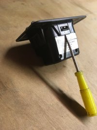
HERE IS THE UNDERSIDE FACE - WITH WHITE STICKER - WHICH HAS JUST A SINGLE CLIP:
IMG_4759.jpg
IMG_4761.jpg

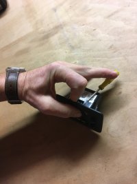
INSERT A SLIM FLAT-BLADED SCREWDRIVER UNDERNEATH THE MAINS BLOCK TO RELEASE THE SINGLE BOTTOM CLIP, WHILST SIMULTANEOUSLY PUSHING GENTLY FROM THE OUTSIDE ON THE BOTTOM EDGE OF THE YELLOW PRINT-ANNOTATED PLUG ABUTMENT FACE - ONCE YOU GET THE SCREWDRIVER IN THE RIGHT POSITION (ALL DONE BY FEEL), THE BLOCK WILL RELEASE EASILY AND 'ROLL' UPWARDS, AT WHICH POINT YOU CAN RELEASE THE UPPER TWO CLIPS IN A SIMILAR FASHION.

THE HARNESS CONNECTOR IS RELEASED BY PULLING UP THE RED SLIDER, AND SPRINGING IN THE YELLOW LEVER BENEATH, SO THAT THE CONNECTOR CAN THEN BE PULLED OUT:
IMG_4782.jpg
 
Last edited:
PART I: HOW TO GET YOUR MAINS PLUG TO SIT FLAT AND THE CORRECT WAY UP IN THE DRIVER'S SEAT 240V SOCKET

SO THIS IS WHAT YOU START WITH - THE OBSTRUCTIVE UPSTAND STOPS THE (UPSIDE-DOWN!) PLUG FROM SEATING, ON OCCASION EVEN FROM MAKING RELIABLE ELECTRICAL CONTACT:
View attachment 101550

AND THIS IS WHAT YOU CAN ACHIEVE INSTEAD - NO UPSTAND; PLUG RIGHT WAY UP, FLAP ORIENTATION IMPROVED:
View attachment 101552
View attachment 101551

START BY SWIVELLING DRIVER'S SEAT / SLIDE BACK TO GET ACCESS TO FWD LEFT QUARTER:
View attachment 101553

YOU NEED TO EXTRACT THE CENTRAL BLACK SHINY MAINS SOCKET (LEAVE [LATCHED] CONNECTOR ATTACHED UNTIL UNIT IS RELEASED)
View attachment 101555
View attachment 101556

HERE IT IS ONCE REMOVED TO SHOW HOW IT IS CLIPPED TO THE FASCIA PLATE - YOURS WILL BE THIS WAY UP SO WITH THE CONNECTOR UPPERMOST AND WITH TWO CLIPS ON THE TOP SIDE TO RELEASE - THIS IS TRICKY, SO BETTER TO RELEASE THE UNDERSIDE FIRST:
View attachment 101557

SO HERE IS THE UNDERSIDE FACE - WITH WHITE STICKER - WHICH HAS JUST A SINGLE CLIP, AS YOU CAN SEE:
View attachment 101558
View attachment 101559

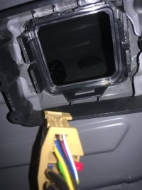
THIS IS WHAT THE INSIDE VIEW WILL BE LIKE ONCE YOU'VE RELEASED THE MAINS BLOCK:
View attachment 101560


PART II: HOW TO GET YOUR MAINS PLUG TO SIT FLAT AND CORRECT WAY UP IN THE DRIVER'S SEAT 240V SOCKET

THIS IS WHAT THE INSIDE VIEW WILL BE LIKE ONCE YOU'VE RELEASED THE MAINS BLOCK:
IMG_4772.jpg

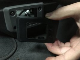
SPRING THE PERIMETER TANGS IN ON THE FACIA PLATE TO RELEASE IT FROM THE SEAT BASE BODY:
IMG_4779.jpg
IMG_4645.JPG
IMG_4646.JPG

REMOVE THE SOCKET COVER FLAP BY PUSHING OUT THE PIN (NOTE CAREFULLY HOW IT REASSEMBLES), DRESS AWAY THE UPSTAND - DIFFICULT TO DO WITHOUT GRAZING THE PERIMETER OF THE FASCIA PLATE, SO TAKE GREAT CARE, AND PREPARE TO REASSEMBLE.
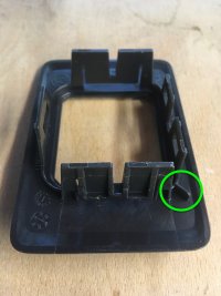
IF WISHING TO INVERT THE PLUG SO THAT THE MAINS CABLE POINTS DOWN, SNIP OFF THE SMALL EAR, RINGED GREEN, WHICH OTHERWISE FORCES YOU TO REASSEMBLE IN THE AS-FACTORY SUPPLIED FASCIA PLATE ORIENTATION :
IMG_4758.jpg
IMG_4646.JPG

- REFIT THE SPRUNG/HINGED SOCKET FLAP ASS'Y
- CLIP THE FASCIA PLATE BACK IN WITH ITS NEW ORIENTATION
- REFIT THE CONNECTOR TO THE MAINS PLUG BODY AND CLOSE THE RED LOCKING SLIDER
- 'POST' THE MAINS BLOCK BACK WITH ITS CORRECT ORIENTATION INTO THE FASCIA PLATE FROM INSIDE THE UNDER-SEAT CAVITY, MAKING SURE THAT THE WIRING HARNESS IS FREE AND UNSTRAINED
- PLUG A MAINS DEVICE IN AND CHECK THAT ALL IS WORKING
- RETURN THE SEAT TO THE DRIVING POSITION

- SIT BACK, SMILE, AND WONDER WHY VW DIDN'T PROVIDE IT TO YOU LIKE THAT IN THE FIRST PLACE!

+ PLEASE LET ME KNOW IF ANYTHING'S UNCLEAR, AND I'LL ADD MORE EXPLANATION AND / OR ANNOTATE THE PICTURES TO TRY AND MAKE THE PROCEDURE CLEARER

++ IF THIS IS ALL TOO FIDDLY - IT MAY WELL BE, DEPENDING ON THE SIZE OF YOUR HANDS AND PATIENCE THRESHOLD - JUST REMOVE THE 4 BOLTS FROM THE SEAT RUNNERS AND LIFT THE SEAT OUT OF THE WAY (WATCH THE HARNESS!!!) WHILST YOU WORK . . . . . IT WILL BE A WHOLE LOT EASIER

THANKS; JS.
 
Last edited:
My T6.1 Ocean is booked in for a replacement socket as plugging anything in to the socket falls out, maybe I need to take a closer look and possibly turn the socket "upside down"
To see if that helps.
A how to remove would be great.
The "HOW-TO" explanation and photo sequence is done - please see latest additions to thread at bottom.
 
The "HOW-TO" explanation and photo sequence is done - please see latest additions to thread at bottom.

The "HOW-TO" explanation and photo sequence is done - please see latest additions to thread at bottom.
Thanks for that, well explained and with photos I will have a look at flipping it at the weekend.
Cheers
 
I’d like to know the reason it’s upside down by design ?
 
I’d like to know the reason it’s upside down by design ?

There's probably a designer in Wolfsburg with a white coat who decided that pointing the cable upwards would be better since it avoids the trip hazard (yeah!)?

It's the obstructive upstand stopping my MacBook charger plug pins mating that made me take it out and modify; only in the course of doing so did I see how easily it would invert, so I did that as a bonus.

I'm learning to live with the green writing now being upside down, especially with the flap closed (;-)), and its hinge in a more intelligent orientation too!
 
Reckon it’s down to the bloke in China that put the sign writing on upside down….. fitter In the factory never been to the UK thought earth at the bottom was normal !
The comment's tongue in cheek, but the matter of 2-tabs topside and 1-tab bottomside on the block, plus the single corner location rib and slot on the fascia plate, both force the upside down orientation - NO, for whatever cock-eyed reason, they wanted it like it is (bless 'em)!
 
Last edited:
The comment's tongue in cheek, but the matter of 2-tabs topside and 1-tab bottomside on the block, plus the single corner location rib and slot on the fascia plate, both force the upside down orientation - NO, for whatever cock-eyed reason, they wanted it like it is (bless 'em)!
Br***t payback!
 
Maybe they thought it was easier to read the ‘upside down’ symbols when you were in a seated position?

Below gives different theories as to what is the correct way up…:

//
The outlet should be oriented with the ground pin up because if the plug comes slightly loose and a metal object were to fall from above, the ground plug, which usually does not carry current, would deflect the object so that it would not hit is live prongs. It is accepted that this idea began in health care facilities where many tools used for patient care are metal. The story goes that hospitals were wired by union electricians and as the unions grew the practice spread to other types of buildings.The outlet should be oriented with the ground pin up because this pin is longer and the plastic around the plug is meatier, so it will help to keep the plug inserted in the outlet.The outlet should be oriented with the ground pin down because a person grabbing the outlet will have their index finger at the bottom side of the plug and the index finger sticks out further than the thumb. Having the ground down will keep a person's index finger from touching the live pins.The outlet should be oriented with the ground pin down because many common household items such as nightlights, timers, and battery chargers are oriented with the ground pin down. In addition, GFCI outlets, which have text on the reset and test buttons, are oriented with the ground pin down (and the text readable).
A quick internet search provides comments that easily debunk any of these theories. The most basic answer is that it truly doesn't matter which way your outlets are oriented. Select the strategy that best works for you.

//
 
The "HOW-TO" explanation and photo sequence is done - please see latest additions to thread at bottom.
Just wondering if anyone has tried this yet, and, of perhaps greater interest, succeeded! . . . . hopefully with a little help from 'above' ;-) ?!
 
Just wondering if anyone has tried this yet, and, of perhaps greater interest, succeeded! . . . . hopefully with a little help from 'above' ;-) ?!
On my “To do list” for Wednesday :thumb
The plug was half hanging out.
Then remembered there was a Thread showing how to dress the sticking out flange.
2FAFCE5D-A78A-46BB-82A4-0ED2E37C7BB7.jpeg
Flange will be dressed Wednesday and will report back.
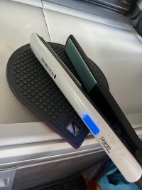
Just tried the wife’s 180w Remington pressed oil infused tongs in and they work a treat 75B81366-B5D3-4906-AFC9-143967EE265F.jpeg
 
Have you seen my wife with her hair up, in what I call a sh1t bun. :oops:
Tongs as high priority as beer and coffee :thumb

No non-essential power tools* permitted on our bus . . . bah humbug!!!

(*jig-saw, cordless drill and MacBook charging obviously excepted . . . )
 
It would be good if you could, as far as I can see the problems have been with the 150watt wall mounted inverter fitted to T6 and earlier.
You've got the new T6.1 300w seat mounted inverter.
I have been using this 150W inverter for charging my OM-1 camera without any problems at all
 
Awesome.
Has taken me only 50 minutes to do this.
I owe you a beer 0AF9566B-45F4-4ED8-A7AF-ACC97E7D78CA.jpegFE07C8CD-9932-4399-9966-0F5750FCFA54.jpeg592533BE-1EA1-42A3-BF92-C9F2ED5CD213.jpeg
 
Nice one - it makes so much sense doesn't it!

Was the guide easy enough to follow? - if you took just 50 minutes, then I guess it was!

See you in the Red Lion later then ;-)
It does, I read your guide twice and struggled for 5 mins only getting the small flat blade in under the first tab. Then once I’d got that and it pulled up, it came out of the top two without much fuss. I tried 5 different plugs in and thought it’s still sticking out the width of the plastic. 1mm. So looked how it was held in, and deduced it didn’t need that much plastic so Stanley’d it out so the plug actually sits flat on top of the socket. It holds in nicely, and won’t push out the fittings at back.
Thank you !
There’s a “local” ish red lion at Sandwell, it’s famous for the tandoori grills. Oh man, makes my mouth water thinking of it. !!
 
PART II: HOW TO GET YOUR MAINS PLUG TO SIT FLAT AND CORRECT WAY UP IN THE DRIVER'S SEAT 240V SOCKET

THIS IS WHAT THE INSIDE VIEW WILL BE LIKE ONCE YOU'VE RELEASED THE MAINS BLOCK:
View attachment 101568

SPRING THE PERIMETER TANGS IN ON THE FACIA PLATE TO RELEASE IT FROM THE SEAT BASE BODY:
View attachment 101563
View attachment 101561
View attachment 101562

REMOVE THE SOCKET COVER FLAP BY PUSHING OUT THE PIN (NOTE CAREFULLY HOW IT REASSEMBLES), DRESS AWAY THE UPSTAND - DIFFICULT TO DO WITHOUT GRAZING THE PERIMETER OF THE FASCIA PLATE, SO TAKE GREAT CARE, AND PREPARE TO REASSEMBLE.
IF WISHING TO INVERT THE PLUG SO THAT THE MAINS CABLE POINTS DOWN, SNIP OFF THE SMALL EAR, RINGED GREEN, WHICH OTHERWISE FORCES YOU TO REASSEMBLE IN THE AS-FACTORY SUPPLIED FASCIA PLATE ORIENTATION :
View attachment 101564
View attachment 101565

- REFIT THE SPRUNG/HINGED SOCKET FLAP ASS'Y
- CLIP THE FASCIA PLATE BACK IN WITH ITS NEW ORIENTATION
- REFIT THE CONNECTOR TO THE MAINS PLUG BODY AND CLOSE THE RED LOCKING SLIDER
- 'POST' THE MAINS BLOCK BACK WITH ITS CORRECT ORIENTATION INTO THE FASCIA PLATE FROM INSIDE THE UNDER-SEAT CAVITY, MAKING SURE THAT THE WIRING HARNESS IS FREE AND UNSTRAINED
- PLUG A MAINS DEVICE IN AND CHECK THAT ALL IS WORKING
- RETURN THE SEAT TO THE DRIVING POSITION

- SIT BACK, SMILE, AND WONDER WHY VW DIDN'T PROVIDE IT TO YOU LIKE THAT IN THE FIRST PLACE!

+ PLEASE LET ME KNOW IF ANYTHING'S UNCLEAR, AND I'LL ADD MORE EXPLANATION AND / OR ANNOTATE THE PICTURES TO TRY AND MAKE THE PROCEDURE CLEARER

++ IF THIS IS ALL TOO FIDDLY - IT MAY WELL BE, DEPENDING ON THE SIZE OF YOUR HANDS AND PATIENCE THRESHOLD - JUST REMOVE THE 4 BOLTS FROM THE SEAT RUNNERS AND LIFT THE SEAT OUT OF THE WAY (WATCH THE HARNESS!!!) WHILST YOU WORK . . . . . IT WILL BE A WHOLE LOT EASIER

THANKS; JS.


+++ I HAVE REALISED, WHILST ON TOUR THIS LAST WEEK AND A HALF, THAT YOU CAN GET ACCESS TO THE BACK SIDE OF THE 240V SOCKET MODULE FAR MORE EASILY THAN I PREVIOUSLY DESCRIBED SIMPLY BY SPINNING THE DRIVER'S SEAT THE FULL 180 deg, SLIDING IT TO THE APPROPRIATE EXTREME, AND TILTING THE BACKREST - SEE PHOTO BELOW. I HOPE THIS HELPS ANYONE WHO STILL HAS THE INCLINATION TO 'FIX' THE ORIGINAL DESIGN ISSUE. THANKS.

IMG_6216.JPG
 
+++ I HAVE REALISED, WHILST ON TOUR THIS LAST WEEK AND A HALF, THAT YOU CAN GET ACCESS TO THE BACK SIDE OF THE 240V SOCKET MODULE FAR MORE EASILY THAN I PREVIOUSLY DESCRIBED SIMPLY BY SPINNING THE DRIVER'S SEAT THE FULL 180 deg, SLIDING IT TO THE APPROPRIATE EXTREME, AND TILTING THE BACKREST - SEE PHOTO BELOW. I HOPE THIS HELPS ANYONE WHO STILL HAS THE INCLINATION TO 'FIX' THE ORIGINAL DESIGN ISSUE. THANKS.

View attachment 107721
Followed your instructions this evening - worked perfectly thanks. Hardest bit was getting the bloody spring for the cover back in the right place. Flange (love that word) removed, and plugs fit nuch better. Many thanks JR.
 
Followed your instructions this evening - worked perfectly thanks. Hardest bit was getting the bloody spring for the cover back in the right place. Flange (love that word) removed, and plugs fit nuch better. Many thanks JR.

Glad you found it useful - it makes so much sense, and is really quite easy to do . . . but yes, that wretched spring is a bit tricky; clearly it only goes one way, but, like you, I found it quite a game - it's one of those assemblies you just pull apart before having looked properly at how it all sits correctly!
 
Glad you found it useful - it makes so much sense, and is really quite easy to do . . . but yes, that wretched spring is a bit tricky; clearly it only goes one way, but, like you, I found it quite a game - it's one of those assemblies you just pull apart before having looked properly at how it all sits correctly!
I knew it would be a PITA so took a close up photo of it before I dismantled it!
 

VW California Club

Back
Top