Hammer
VIP Member
Hi All
Just completed changing motion sensor to touch button so below is process and what’s needed so people can decide if they are comfortable doing.
Purchased new switch from amazon but you can get on ebay too. Remember to make sure you get 12V version
https://www.amazon.co.uk/dp/B095PSDRHQ/?tag=unique09f-21
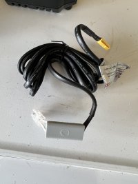
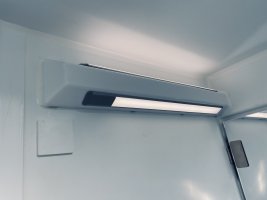
firstly you need to remove the light strip by simply pulling out, then unplug two connector. The black plug needs the small tab pulling black to release.
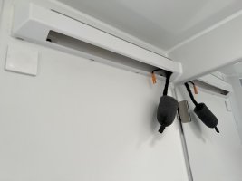
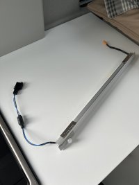
Remove the two screws on end of light strip (sensor end)
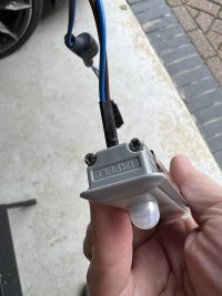
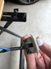
You should be able to pull off the defuser (it just clips in)
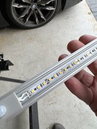
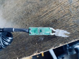
You will see two wires soldered to the light strip, unsolder these and remove sensor
The new sensor has a plastic connector which cant be used so needs cutting off to leave the two white wires.
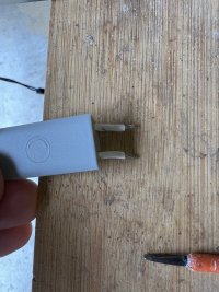
Solder these onto led light strip (note the cables are a bit thicker so is tight fit)
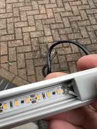
You will now need to cut the black cable on the new switch to a shorter length and expose the two wires. plus you will need to cut the cables off the old sensor and solder these to the new switch.
This point caused me issues as it didn’t work and after bit of messing around noticed the black cable from the 12V feed was + and the brown was - so had to reverse the wires as i had used red to brown and black to blue!!
Correct order for my van (suggest you check your own in case this is not normal) Red from new switch to Blue and Black from new switch to brown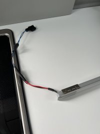
Light now just needs plugging in and testing
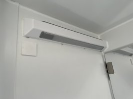
Hope this helps anyone wanting to undertake this project but please only do if you are happy taking risk.
Just completed changing motion sensor to touch button so below is process and what’s needed so people can decide if they are comfortable doing.
Purchased new switch from amazon but you can get on ebay too. Remember to make sure you get 12V version
https://www.amazon.co.uk/dp/B095PSDRHQ/?tag=unique09f-21

firstly you need to remove the light strip by simply pulling out, then unplug two connector. The black plug needs the small tab pulling black to release.


Remove the two screws on end of light strip (sensor end)


You should be able to pull off the defuser (it just clips in)

You will see two wires soldered to the light strip, unsolder these and remove sensor
The new sensor has a plastic connector which cant be used so needs cutting off to leave the two white wires.

Solder these onto led light strip (note the cables are a bit thicker so is tight fit)

You will now need to cut the black cable on the new switch to a shorter length and expose the two wires. plus you will need to cut the cables off the old sensor and solder these to the new switch.
This point caused me issues as it didn’t work and after bit of messing around noticed the black cable from the 12V feed was + and the brown was - so had to reverse the wires as i had used red to brown and black to blue!!
Correct order for my van (suggest you check your own in case this is not normal) Red from new switch to Blue and Black from new switch to brown

Light now just needs plugging in and testing

Hope this helps anyone wanting to undertake this project but please only do if you are happy taking risk.


