Below is a picture of the rear sensor before I touched it.
View attachment 78720The blue arrow shows the front hose that is looped around the back of the hydraulic ram. This can be unclipped which makes it easy to twist the hose to replace the front sensors. You can see the rear hose directly above the rear sensor with “2” on it. Even removing this is difficult. You will probably destroy it getting it out. It was suggested to me that I didn’t want that hose to pop out or bad things would happen. The good news is they seem to be securely fitted.
When I got it out and started to remove the electrical tape I found that this wiring was more complicated. There were still two wires going to the sensor but there were connectors under the tape with two wires joining into one before going to the sensor. This meant a little care was needed about where I was going to make my join.
View attachment 78724
I cut the wire and put some tape around the first 10cm of the new sensor and cut and stripped the wires ready to connect.
It became clear that the only way I was going to be able to get the new sensor in, was to snap off the bits of plastic you can see above either side of the “2” and slide it in from the back. After these plastic clips were snapped I also needed to use a sharp pen knife to really remove all the remaining tiny bits of plastic where I had snapped them off. This might not seem great but I assure you when these sensors are in place there is no way they’re ever coming out. Here you can see I tried to get it in with one piece of the clip removed but it would not work.
View attachment 78721
With both bits removed and trimmed with a sharp knife, it was possible to push it through from the back.
View attachment 78722
You can see that with the rear clips remaining and the plastic bit where the wires are, in the central channel it’s not going anywhere. I then connected the wires and covered in tape as before.
After doing the two rear sensors I finished with the front one. Here you can see how much easier it is to move the hose out of the way.
View attachment 78725
This sensor wasn’t rusted but was covered with a white crystalline dust that suggested some corrosion or reaction. I cleaned this all away.
View attachment 78726
The final job before the plastic cover goes back on. Reasonably tidy and not that dissimilar to how it was.
View attachment 78727
I now made sure I hadn’t left any screwdrivers etc on the roof and reconnected the batteries.
(When I reconnected everything after replacing the first sensor, at the end of day one, there was a few worrying electrical shenanigans. The engine wouldn’t start first time; the control unit was flashing and wouldn’t give me the main menu until I set the clock; error 7001 came up which means loss of power. I think my ignition often doesn’t like starting until I’ve jiggled the steering wheel and engaged the steering lock. Eventually it started, but, as I said before, replacing the one sensor didn’t work. I plugged the van in overnight which cleared 7001.)
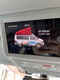
So after replacing the other 3 sensors and reconnecting the batteries I plugged in to the mains to make sure all was charged. I then went for a walk for an hour, contemplating success and failure. With it looking like it was about to rain I was forced into seeing if it had all worked. I think I had to set the clock again. I checked diagnostics but no errors this time. I turned the key and lowered the roof. The van made the usual 3 noises and the final locking one suddenly stopped. Like it should! The first time in months, it was back to normal. Success!! The roof down symbol was there.
View attachment 78728
I went for a drive to make sure the chimes wouldn’t reappear. They didn’t.
One odd quirk of the roof thinking it’s up, is that you can’t turn off the control module. I checked this and it turned off, so again, everything was back to normal.
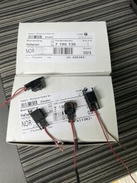
So the 4 sensors cost me €100 on eBay and I spent about £30 on some tools. The sensors are now £58.67 for 4 from bmwsupply.co.uk. I’ve just ordered another 4 as my van is a 2008 T5 and I can I imagine having to do this again sometime, ten years from now.
It took me 6 hours to replace the first sensor but an hour was lost borrowing a spline socket to remove the seat, it rained for an hour and several people wandered past and engaged me in conversation. The first attempt was quite fiddly and without the wire stripper, which was an absolute life-saver. The number 2 slot was great for stripping the very fine wire. The second day I replaced the other 3 sensors in 4 hours.
View attachment 78729
I’ve heard it suggested a VW roof loom costs £150-£250 just as a part. The labour charges could send this upto £3000, depending on the dealer.
If there was a great dealer near me, I would have ‘happily’ have paid them maybe £600-£1000 to fix this. I love our van and will always pay whatever to have it maintained properly. I wouldn’t however, want to pay a dealer £3000 to pull out the roof lining for no good reason and generally fumble about.
In all honesty I am still amazed I fixed it!


